AIR CONDITIONING SYSTEM, Diagnostic DTC:B14AA
| DTC Code | DTC Name |
|---|---|
| B14AA | Glass Humidity Sensor Circuit |
DESCRIPTION
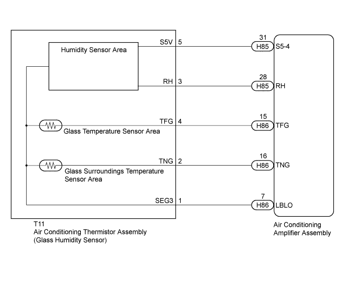
The air conditioning amplifier assembly detects the windshield glass humidity from this circuit. The air conditioning amplifier assembly applies voltage to the air conditioning thermistor assembly (glass humidity sensor). As the humidity rises, the voltage output of the sensor increases. The air conditioning amplifier assembly detects the voltage change as the humidity changes.
| DTC No. | DTC Detection Condition | Trouble Area |
|---|---|---|
| B14AA | Open or short in glass humidity sensor circuit |
|
Tech Tips
The whole air conditioning thermistor assembly should be replaced if the glass humidity sensor is malfunctioning.
WIRING DIAGRAM
INSPECTION PROCEDURE
PROCEDURE
-
READ VALUE USING INTELLIGENT TESTER
-
Connect the intelligent tester to the DLC3.
-
Turn the power switch on (IG).
-
Turn the intelligent tester on.
-
Enter the following menus: Body / Air Conditioner / Data List.
-
Check the value(s) by referring to the table below.
Air Conditioner Tester Display Measurement Item/Range Normal Condition Diagnostic Note Glass Humidity Glass humidity/
Min.: 0 (%)
Max.: 200 (%)
Actual glass humidity displayed - OK The display is as specified in the Normal Condition column. Result Result Proceed to NG A OK (When troubleshooting according to Problem Symptoms Table) B OK (When troubleshooting according to the DTC) C
B 
PROCEED TO NEXT SUSPECTED AREA SHOWN IN PROBLEM SYMPTOMS TABLE Click here
C
REPLACE AIR CONDITIONING AMPLIFIER ASSEMBLY Click here
A 
-
-
INSPECT AIR CONDITIONING AMPLIFIER ASSEMBLY
-
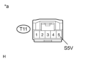
Text in Illustration *a Front view of wire harness connector
(to Air Conditioning Thermistor Assembly (Glass Humidity Sensor))
Disconnect the T11 air conditioning thermistor assembly (glass humidity sensor) connector.
-
Measure the voltage according to the value(s) in the table below.
Standard Voltage Tester Connection Condition Specified Condition T11-5 (S5V) - Body ground Power switch on (IG) 4.5 to 5.5 V
NG 
CHECK HARNESS AND CONNECTOR (AIR CONDITIONING AMPLIFIER - GLASS HUMIDITY SENSOR) Click here
OK
-
-
INSPECT AIR CONDITIONING THERMISTOR ASSEMBLY (GLASS HUMIDITY SENSOR)
-
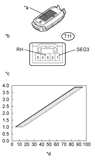
Text in Illustration *a Heat Conduction Sheet Part *b Component with harness connected
(Air Conditioning Thermistor Assembly (Glass Humidity Sensor))
*c Voltage (V) *d Relative Humidity (%) Remove the air conditioning thermistor assembly (glass humidity sensor) with the connector still connected Click here.
-
Turn the power switch on (IG).
-
Measure the voltage according to the value(s) in the table below.
Standard Voltage Tester Connection Condition Specified Condition T11-1 (SEG3) - T11-3 (RH) Power switch on (IG)
Humidity is 5 to 15%
Approximately 1.01 V T11-1 (SEG3) - T11-3 (RH) Power switch on (IG)
Humidity is 15 to 25%
Approximately 1.37 V T11-1 (SEG3) - T11-3 (RH) Power switch on (IG)
Humidity is 25 to 35%
Approximately 1.73 V T11-1 (SEG3) - T11-3 (RH) Power switch on (IG)
Humidity is 35 to 45%
Approximately 2.09 V T11-1 (SEG3) - T11-3 (RH) Power switch on (IG)
Humidity is 45 to 55%
Approximately 2.45 V T11-1 (SEG3) - T11-3 (RH) Power switch on (IG)
Humidity is 55 to 65%
Approximately 2.81 V T11-1 (SEG3) - T11-3 (RH) Power switch on (IG)
Humidity is 65 to 75%
Approximately 3.17 V T11-1 (SEG3) - T11-3 (RH) Power switch on (IG)
Humidity is 75 to 85%
Approximately 3.53 V T11-1 (SEG3) - T11-3 (RH) Power switch on (IG)
Humidity is 85 to 95%
Approximately 3.89 V Note
-
Do not touch the sensor as body heat will affect the inspection results. When performing the inspection, hold the sensor by its connector.
-
Allow the sensor to acclimate to the ambient temperature and humidity before performing the inspection.
-
The specified voltages in the table above are based on inspections performed when the ambient temperature is 25°C (77°F).
Tech Tips
As the humidity increases, the voltage increases (see the graph).
-
NG
REPLACE AIR CONDITIONING THERMISTOR ASSEMBLY Click here
OK
-
-
CHECK HARNESS AND CONNECTOR (AIR CONDITIONING AMPLIFIER - GLASS HUMIDITY SENSOR)
-
Disconnect the T11 air conditioning thermistor assembly (glass humidity sensor) connector.
-
Disconnect the H85 and H86 air conditioning amplifier assembly connectors.
-
Measure the resistance according to the value(s) in the table below.
Standard Resistance Tester Connection Condition Specified Condition T11-3 (RH) - H85-28 (RH) Always Below 1 Ω T11-3 (RH) - Body ground Always 10 kΩ or higher T11-1 (SEG3) - H86-7 (LBLO) Always Below 1 Ω T11-1 (SEG3) - Body ground Always 10 kΩ or higher
NG
REPAIR OR REPLACE HARNESS OR CONNECTOR
OK 
REPLACE AIR CONDITIONING AMPLIFIER ASSEMBLY Click here
-
-
CHECK HARNESS AND CONNECTOR (AIR CONDITIONING AMPLIFIER - GLASS HUMIDITY SENSOR)
-
Disconnect the T11 air conditioning thermistor assembly (glass humidity sensor) connector.
-
Disconnect the H85 air conditioning amplifier assembly connector.
-
Measure the resistance according to the value(s) in the table below.
Standard Resistance Tester Connection Condition Specified Condition T11-5 (S5V) - H85-31 (S5-4) Always Below 1 Ω T11-5 (S5V) - Body ground Always 10 kΩ or higher
NG
REPAIR OR REPLACE HARNESS OR CONNECTOR
OK
REPLACE AIR CONDITIONING AMPLIFIER ASSEMBLY Click here
-