FRONT POWER SEAT CONTROL SYSTEM (w/ Memory), Diagnostic DTC:B2658
| DTC Code | DTC Name |
|---|---|
| B2658 | Short in Sensor with Motor Power Supply Circuit |
DESCRIPTION
This DTC is stored when a power seat motor operates (a position control sensor is being supplied with power) and the power supply voltage does not rise to the specified value.
| DTC Code | DTC Detection Condition | Trouble Area |
|---|---|---|
| B2658 | A problem with the voltage supplied to the position control sensor. |
|
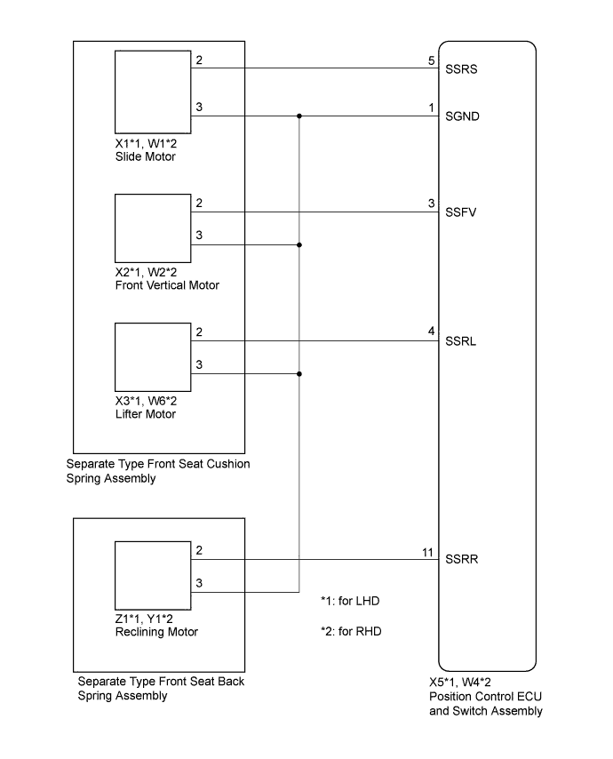
WIRING DIAGRAM
INSPECTION PROCEDURE
PROCEDURE
-
CHECK FOR DTC
-
Clear the DTCs Click here.
-
Check for DTCs Click here.
OK DTC B2658 is not output.
NG 
CHECK HARNESS AND CONNECTOR (POSITION CONTROL ECU AND SWITCH ASSEMBLY - SLIDE MOTOR) Click here
OK 
USE SIMULATION METHOD TO CHECK Click here
-
-
CHECK HARNESS AND CONNECTOR (POSITION CONTROL ECU AND SWITCH ASSEMBLY - SLIDE MOTOR)
-
Disconnect the X5*1 or W4*2 position control ECU and switch assembly connector.
-
Disconnect the X1*1 or W1*2 slide motor connector.
-
*1: for LHD
-
*2: for RHD
-
-
Measure the resistance according to the value(s) in the table below.
Standard Resistance for LHD Tester Connection Condition Specified Condition X5-5 (SSRS) - X1-2 Always Below 1 Ω X5-1 (SGND) - X1-3 Always Below 1 Ω X5-5 (SSRS) - X5-1 (SGND) Always 10 kΩ or higher X5-5 (SSRS) - Body ground Always 10 kΩ or higher X5-1 (SGND) - Body ground Always 10 kΩ or higher for RHD Tester Connection Condition Specified Condition W4-5 (SSRS) - W1-2 Always Below 1 Ω W4-1 (SGND) - W1-3 Always Below 1 Ω W4-5 (SSRS) - W4-1 (SGND) Always 10 kΩ or higher W4-5 (SSRS) - Body ground Always 10 kΩ or higher W4-1 (SGND) - Body ground Always 10 kΩ or higher
NG 
REPAIR OR REPLACE HARNESS OR CONNECTOR
OK 
-
-
CHECK POSITION CONTROL ECU AND SWITCH ASSEMBLY (SLIDE MOTOR CIRCUIT)
-
Measure the voltage according to the value(s) in the table below.
Standard Voltage for LHD Tester Connection Switch Condition Specified Condition X1-2 - X1-3 Sliding switch on 4.8 to 5.1 V for RHD Tester Connection Switch Condition Specified Condition W1-2 - W1-3 Sliding switch on 4.8 to 5.1 V
NG
REPLACE POSITION CONTROL ECU AND SWITCH ASSEMBLY Click here
OK
-
-
CHECK HARNESS AND CONNECTOR (POSITION CONTROL ECU AND SWITCH - FRONT VERTICAL MOTOR)
-
Disconnect the X2*1 or W2*2 front vertical motor connector.
-
*1: for LHD
-
*2: for RHD
-
-
Measure the resistance according to the value(s) in the table below.
Standard Resistance for LHD Tester Connection Condition Specified Condition X5-3 (SSFV) - X2-2 Always Below 1 Ω X5-1 (SGND) - X2-3 Always Below 1 Ω X5-3 (SSFV) - X5-1 (SGND) Always 10 kΩ or higher X5-3 (SSFV) - Body ground Always 10 kΩ or higher X5-1 (SGND) - Body ground Always 10 kΩ or higher for RHD Tester Connection Condition Specified Condition W4-3 (SSFV) - W2-2 Always Below 1 Ω W4-1 (SGND) - W2-3 Always Below 1 Ω W4-3 (SSFV) - W4-1 (SGND) Always 10 kΩ or higher W4-3 (SSFV) - Body ground Always 10 kΩ or higher W4-1 (SGND) - Body ground Always 10 kΩ or higher
NG
REPAIR OR REPLACE HARNESS OR CONNECTOR
OK
-
-
CHECK POSITION CONTROL ECU AND SWITCH ASSEMBLY (FRONT VERTICAL MOTOR CIRCUIT)
-
Measure the voltage according to the value(s) in the table below.
Standard Voltage for LHD Tester Connection Switch Condition Specified Condition X2-2 - X2-3 Front vertical switch on 4.8 to 5.1 V for RHD Tester Connection Switch Condition Specified Condition W2-2 - W2-3 Front vertical switch on 4.8 to 5.1 V
NG
REPLACE POSITION CONTROL ECU AND SWITCH ASSEMBLY Click here
OK
-
-
CHECK HARNESS AND CONNECTOR (POSITION CONTROL ECU AND SWITCH ASSEMBLY - LIFTER MOTOR)
-
Disconnect the X3*1 or W6*2 lifter motor connector.
-
*1: for LHD
-
*2: for RHD
-
-
Measure the resistance according to the value(s) in the table below.
Standard Resistance for LHD Tester Connection Condition Specified Condition X5-4 (SSRL) - X3-2 Always Below 1 Ω X5-1 (SGND) - X3-3 Always Below 1 Ω X5-4 (SSRL) - X5-1 (SGND) Always 10 kΩ or higher X5-4 (SSRL) - Body ground Always 10 kΩ or higher X5-1 (SGND) - Body ground Always 10 kΩ or higher for RHD Tester Connection Condition Specified Condition W4-4 (SSRL) - W6-2 Always Below 1 Ω W4-1 (SGND) - W6-3 Always Below 1 Ω W4-4 (SSRL) - W4-1 (SGND) Always 10 kΩ or higher W4-4 (SSRL) - Body ground Always 10 kΩ or higher W4-1 (SGND) - Body ground Always 10 kΩ or higher
NG
REPAIR OR REPLACE HARNESS OR CONNECTOR
OK
-
-
CHECK POSITION CONTROL ECU AND SWITCH ASSEMBLY (LIFTER MOTOR CIRCUIT)
-
Measure the voltage according to the value(s) in the table below.
Standard Voltage for LHD Tester Connection Switch Condition Specified Condition X3-2 - X3-3 Lifter switch on 4.8 to 5.1 V for RHD Tester Connection Switch Condition Specified Condition W6-2 - W6-3 Lifter switch on 4.8 to 5.1 V
NG
REPLACE POSITION CONTROL ECU AND SWITCH ASSEMBLY Click here
OK
-
-
REPLACE SEPARATE TYPE FRONT SEAT CUSHION SPRING ASSEMBLY
-
Replace the separate type front seat cushion spring assembly Click here.
-
Clear the DTCs Click here.
-
Check for DTCs Click here.
OK DTC B2658 is not output.
NG
CHECK HARNESS AND CONNECTOR (POSITION CONTROL ECU AND SWITCH ASSEMBLY - RECLINING MOTOR) Click here
OK
END (SEPARATE TYPE FRONT SEAT CUSHION SPRING WAS DEFECTIVE)
-
-
CHECK HARNESS AND CONNECTOR (POSITION CONTROL ECU AND SWITCH ASSEMBLY - RECLINING MOTOR)
-
Disconnect the X5*1 or W4*2 position control ECU and switch assembly connector.
-
Disconnect the Z1*1 or Y1*2 reclining motor connector.
-
*1: for LHD
-
*2: for RHD
-
-
Measure the resistance according to the value(s) in the table below.
Standard Resistance for LHD Tester Connection Condition Specified Condition X5-11 (SSRR) - Z1-2 Always Below 1 Ω X5-1 (SGND) - Z1-3 Always Below 1 Ω X5-11 (SSRR) - X5-1 (SGND) Always 10 kΩ or higher X5-11 (SSRR) - Body ground Always 10 kΩ or higher X5-1 (SGND) - Body ground Always 10 kΩ or higher for RHD Tester Connection Condition Specified Condition W4-11 (SSRR) - Y1-2 Always Below 1 Ω W4-1 (SGND) - Y1-3 Always Below 1 Ω W4-11 (SSRR) - W4-1 (SGND) Always 10 kΩ or higher W4-11 (SSRR) - Body ground Always 10 kΩ or higher W4-1 (SGND) - Body ground Always 10 kΩ or higher
NG
REPAIR OR REPLACE HARNESS OR CONNECTOR
OK
-
-
CHECK POSITION CONTROL ECU AND SWITCH ASSEMBLY (RECLINING MOTOR CIRCUIT)
-
Measure the voltage according to the value(s) in the table below.
Standard Voltage for LHD Tester Connection Switch Condition Specified Condition Z1-2 - Z1-3 Reclining switch on 4.8 to 5.1 V for RHD Tester Connection Switch Condition Specified Condition Y1-2 - Y1-3 Reclining switch on 4.8 to 5.1 V
NG
REPLACE POSITION CONTROL ECU AND SWITCH ASSEMBLY Click here
OK
-
-
REPLACE SEPARATE TYPE FRONT SEAT BACK SPRING ASSEMBLY
-
Replace the separate type front seat back spring assembly Click here.
-
Clear the DTCs Click here.
-
Check for DTCs Click here.
OK DTC B2658 is not output.
NG
REPLACE POSITION CONTROL ECU AND SWITCH ASSEMBLY Click here
OK
END (SEPARATE TYPE FRONT SEAT BACK SPRING ASSEMBLY WAS DEFECTIVE)
-