PRE-CRASH SAFETY SYSTEM, Diagnostic DTC:U0235
| DTC Code | DTC Name |
|---|---|
| U0235 | Lost Communication with Cruise Control Front Distance Range Sensor |
DESCRIPTION
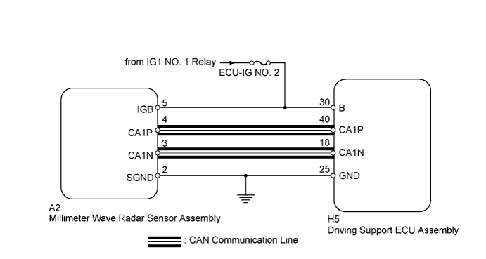
The driving support ECU assembly sends information on steering angle and steering direction to the millimeter wave radar sensor assembly. The millimeter wave radar sensor assembly then sends information on the presence, distance, and relative speed of objects ahead to the driving support ECU assembly. The driving support ECU assembly sends this information to the power management control ECU and performs cruise control.
| DTC No. | DTC Detection Condition | Trouble Area |
|---|---|---|
| U0235 | When the power switch is on (IG), a communication error from the millimeter wave radar sensor assembly to the driving support ECU assembly is detected for approx. 1 second. |
|
WIRING DIAGRAM
INSPECTION PROCEDURE
Note
-
When the millimeter wave radar sensor assembly is replaced with a new one, adjustment of the radar sensor beam axis must be performed Click here.
-
Confirm that the connector is securely connected, as a partially connected connector is suspected for the cause of this DTC.
PROCEDURE
-
CHECK CAN COMMUNICATION SYSTEM
-
Using the intelligent tester to check if the CAN communication system is functioning normally Click here.
OK CAN communication system DTC is not output.
NG 
GO TO CAN COMMUNICATION SYSTEM Click here
OK 
-
-
CHECK HARNESS AND CONNECTOR (DRIVING SUPPORT ECU ASSEMBLY POWER SOURCE)
-
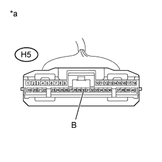
Text in Illustration *a Front view of wire harness connector
(to Driving Support ECU Assembly)
Disconnect the driving support ECU assembly connector.
-
Turn the power switch on (IG).
-
Measure the voltage according to the value(s) in the table below.
Standard Voltage Tester Connection Switch Condition Specified Condition H5-30 (B) - Body ground Power switch on (IG) 11 to 14 V -
Reconnect the driving support ECU assembly connector.
NG
REPAIR OR REPLACE HARNESS OR CONNECTOR
OK
-
-
CHECK HARNESS AND CONNECTOR (DRIVING SUPPORT ECU ASSEMBLY - BODY GROUND)
-
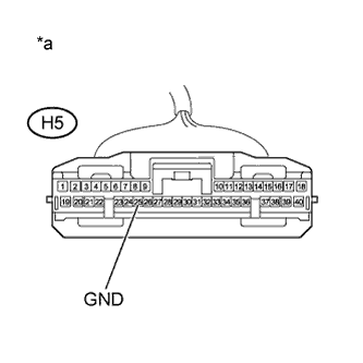
Text in Illustration *a Front view of wire harness connector
(to Driving Support ECU Assembly)
Disconnect the driving support ECU assembly connector.
-
Measure the resistance according to the value(s) in the table below.
Standard Resistance Tester Connection Condition Specified Condition H5-25 (GND) - Body ground Always Below 1 Ω -
Reconnect the driving support ECU assembly connector.
NG
REPAIR OR REPLACE HARNESS OR CONNECTOR
OK
-
-
REPLACE DRIVING SUPPORT ECU ASSEMBLY
-
Replace the driving support ECU assembly Click here.
NEXT
-
-
CHECK DTC OUTPUT
-
Clear the DTCs Click here.
-
Turn the power switch on (IG).
-
Check if the same DTC is output Click here.
Result Result Proceed to DTC U0235 is not output A DTC U0235 is output B
B
REPLACE MILLIMETER WAVE RADAR SENSOR ASSEMBLY Click here
A 
END
-