REAR AIRBAG SENSOR INSTALLATION
Tech Tips
-
Use the same procedure for the RH side and LH side.
-
The procedure listed below is for the LH side.
-
INSTALL NO. 2 SIDE AIRBAG SENSOR ASSEMBLY
-
Check that the power switch is off.
-
Check that the cable is disconnected from the negative (-) auxiliary battery terminal.
CAUTION:
Wait at least 90 seconds after disconnecting the cable from the negative (-) auxiliary battery terminal to disable the SRS system.
-
Insert the pin (stopper) into the body hole to install the No. 2 side airbag sensor assembly to the vehicle with the nut.
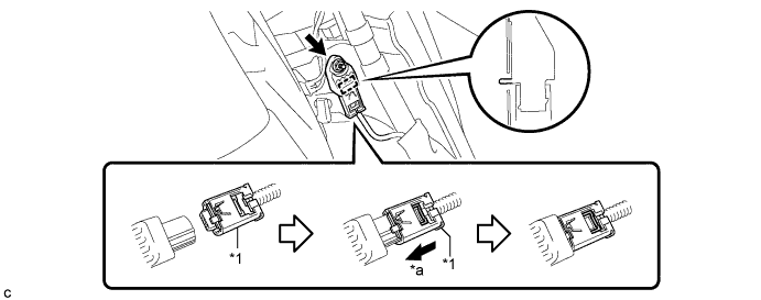
Text in Illustration *1 Outer Connector Locking Sleeve - - *a Slide - - - Torque:
- 9.0 N*m { 92 kgf*cm, 80 in.*lbf }
Note
-
If the No. 2 side airbag sensor assembly has been dropped, or there are any cracks, dents or other defects in the case or connector, replace it with a new one.
-
When installing the No. 2 side airbag sensor assembly, be careful that the SRS wiring does not interfere with or is not pinched between other parts.
-
Make sure that the pin (stopper) is securely inserted into the body hole.
-
Tighten the nut while holding the No. 2 side airbag sensor assembly because the No. 2 side airbag sensor assembly pin (stopper) is easily damaged.
-
Connect the connector to the No. 2 side airbag sensor assembly.
Note
When connecting any airbag connector, take care not to damage the airbag wire harness.
-
Connect the connector as shown in the illustration (when locking, make sure that the outer connector locking sleeve returns to its original position and a click sound can be heard).
-
-
Check that there is no looseness in the installation parts of the No. 2 side airbag sensor assembly.
-
-
INSTALL REAR SEAT SIDE GARNISH
-
Engage the 6 claws.
-
Install the rear seat side garnish LH with the clip.
-
-
INSTALL REAR SEAT SIDE COVER RH (for RH Side)
-
Engage the 3 claws and 2 clips to install the rear seat side cover RH.
-
-
INSTALL REAR DOOR SCUFF PLATE
-
Engage the 4 claws, 2 guides and 2 clips to install the rear door scuff plate LH.
-
-
INSTALL REAR SEAT ASSEMBLY
-
CONNECT CABLE TO NEGATIVE AUXILIARY BATTERY TERMINAL
Note
When disconnecting the cable, some systems need to be initialized after the cable is reconnected Click here.
-
INSTALL REAR FLOOR BOARD UPPER NO. 3 PLATE
-
Engage the 4 claws and 2 guides to install the rear floor board upper No. 3 plate.
-
-
INSTALL DECK FLOOR BOX RH
-
Engage the 6 guides.
-
Install the deck floor box RH with the clip.
-
-
INSTALL REAR NO. 3 FLOOR BOARD
-
Install the rear No. 3 floor board.
-
-
INSTALL REAR DECK FLOOR BOX
-
Install the rear deck floor box.
-
-
INSTALL REAR NO. 2 FLOOR BOARD
-
Install the rear No. 2 floor board.
-
-
PERFORM DIAGNOSTIC SYSTEM CHECK
-
INSPECT SRS WARNING LIGHT