AIRBAG SYSTEM, Diagnostic DTC:B1653/35

| DTC Code | DTC Name |
|---|---|
| B1653/35 | Seat Position Airbag Sensor Circuit Malfunction |
DESCRIPTION
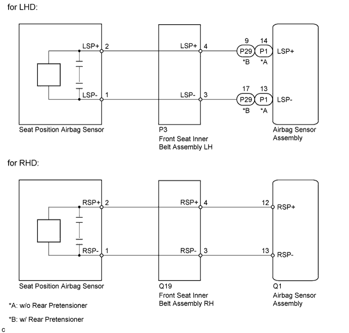
The seat position airbag sensor circuit consists of the airbag sensor assembly, front seat inner belt assembly LH (for LHD) or front seat inner belt assembly RH (for RHD) and seat position airbag sensor.
DTC B1653/35 is stored when a malfunction is detected in the seat position airbag sensor circuit.
| DTC No. | DTC Detection Condition | Trouble Area |
|---|---|---|
| B1653/35 |
|
for LHD:
for RHD: |
WIRING DIAGRAM
INSPECTION PROCEDURE
Note
After turning the power switch off, waiting time may be required before disconnecting the cable from the negative (-) auxiliary battery terminal. Therefore, make sure to read the disconnecting the cable from the negative (-) auxiliary battery terminal notices before proceeding with work Click here.
PROCEDURE
-
CHECK VEHICLE CONDITION
-
Check vehicle condition.
Result Result Proceed to LHD A RHD B
B 
CHECK CONNECTORS Click here
A 
-
-
CHECK CONNECTORS
-
Turn the power switch off.
-
Disconnect the cable from the negative (-) auxiliary battery terminal.
CAUTION:
Wait at least 90 seconds after disconnecting the cable from the negative (-) auxiliary battery terminal to disable the SRS system.
-
Check that the connectors are properly connected to the airbag sensor assembly, front seat inner belt assembly LH and seat position airbag sensor.
OK The connectors are properly connected. Tech Tips
If the connectors are not connected securely, reconnect the connectors and proceed to the next inspection.
-
Disconnect the connectors from the airbag sensor assembly, front seat inner belt assembly LH and seat position airbag sensor.
-
Check that the terminals of the connectors are not damaged.
OK The terminals are not deformed or damaged.
NG 
REPLACE WIRE HARNESS
OK
-
-
CHECK SEAT POSITION AIRBAG SENSOR CIRCUIT (OPEN)
- SST
- 09843-18040
-
w/o Rear Pretensioner
-
Connect the connectors to the front seat inner belt assembly LH and floor wire.
-
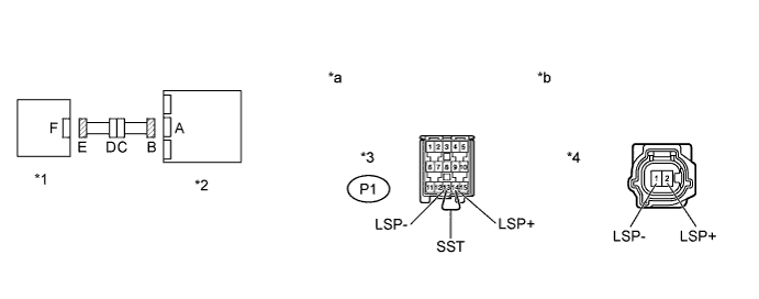
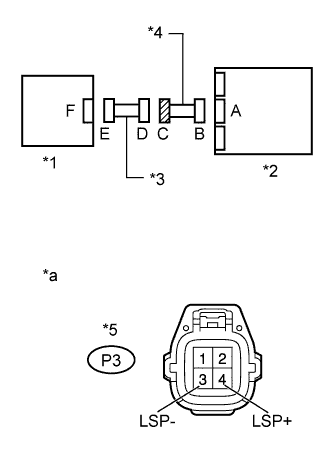
Using SST, connect terminals 14 (LSP+) and 13 (LSP-) of connector B.
Note
Do not forcibly insert SST into the terminals of the connector when connecting the wire.
-
Measure the resistance according to the value(s) in the table below.
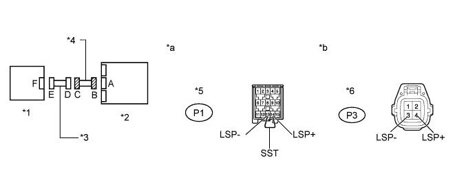
Standard Resistance Tester Connection Condition Specified Condition 2 (LSP+) - 1 (LSP-) Always Below 1 Ω Text in Illustration *1 Seat Position Airbag Sensor *2 Airbag Sensor Assembly *3 Connector B *4 Connector E *a Front view of wire harness connector
(to Airbag Sensor Assembly)
*b Front view of wire harness connector
(to Seat Position Airbag Sensor)
- SST
- 09843-18040
-
-
w/ Rear Pretensioner
-
Connect the connectors to the front seat inner belt assembly LH and floor wire.
-
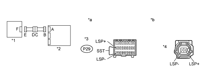
Using SST, connect terminals 9 (LSP+) and 17 (LSP-) of connector B.
Note
Do not forcibly insert SST into the terminals of the connector when connecting the wire.
-
Measure the resistance according to the value(s) in the table below.
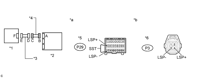
Standard Resistance Tester Connection Condition Specified Condition 2 (LSP+) - 1 (LSP-) Always Below 1 Ω Text in Illustration *1 Seat Position Airbag Sensor *2 Airbag Sensor Assembly *3 Connector B *4 Connector E *a Front view of wire harness connector
(to Airbag Sensor Assembly)
*b Front view of wire harness connector
(to Seat Position Airbag Sensor)
-
NG
CHECK FLOOR WIRE (OPEN) Click here
OK
-
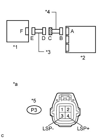
CHECK SEAT POSITION AIRBAG SENSOR CIRCUIT (SHORT)
-
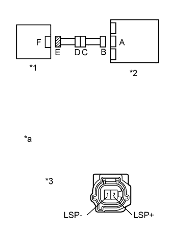
Text in Illustration *1 Seat Position Airbag Sensor *2 Airbag Sensor Assembly *3 Connector E *a Front view of wire harness connector
(to Seat Position Airbag Sensor)
w/o Rear Pretensioner
-
Disconnect SST from connector B.
-
Measure the resistance according to the value(s) in the table below.
Standard Resistance Tester Connection Condition Specified Condition 2 (LSP+) - 1 (LSP-) Always 1 MΩ or higher
-
-
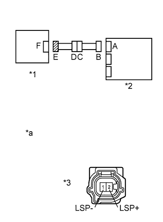
Text in Illustration *1 Seat Position Airbag Sensor *2 Airbag Sensor Assembly *3 Connector E *a Front view of wire harness connector
(to Seat Position Airbag Sensor)
w/ Rear Pretensioner
-
Disconnect SST from connector B.
-
Measure the resistance according to the value(s) in the table below.
Standard Resistance Tester Connection Condition Specified Condition 2 (LSP+) - 1 (LSP-) Always 1 MΩ or higher
-
NG
CHECK FLOOR WIRE (SHORT) Click here
OK
-
-
CHECK SEAT POSITION AIRBAG SENSOR CIRCUIT (SHORT TO B+)
-
Text in Illustration *1 Seat Position Airbag Sensor *2 Airbag Sensor Assembly *3 Connector E *a Front view of wire harness connector
(to Seat Position Airbag Sensor)
w/o Rear Pretensioner
-
Connect the cable to the negative (-) auxiliary battery terminal.
-
Turn the power switch on (IG).
-
Measure the voltage according to the value(s) in the table below.
Standard Voltage Tester Connection Switch Condition Specified Condition 2 (LSP+) - Body ground Power switch on (IG) Below 1 V 1 (LSP-) - Body ground Power switch on (IG) Below 1 V
-
-
Text in Illustration *1 Seat Position Airbag Sensor *2 Airbag Sensor Assembly *3 Connector E *a Front view of wire harness connector
(to Seat Position Airbag Sensor)
w/ Rear Pretensioner
-
Connect the cable to the negative (-) auxiliary battery terminal.
-
Turn the power switch on (IG).
-
Measure the voltage according to the value(s) in the table below.
Standard Voltage Tester Connection Switch Condition Specified Condition 2 (LSP+) - Body ground Power switch on (IG) Below 1 V 1 (LSP-) - Body ground Power switch on (IG) Below 1 V
-
NG
CHECK FLOOR WIRE (SHORT TO B+) Click here
OK
-
-
CHECK SEAT POSITION AIRBAG SENSOR CIRCUIT (SHORT TO GROUND)
-
Text in Illustration *1 Seat Position Airbag Sensor *2 Airbag Sensor Assembly *3 Connector E *a Front view of wire harness connector
(to Seat Position Airbag Sensor)
w/o Rear Pretensioner
-
Turn the power switch off.
-
Disconnect the cable from the negative (-) auxiliary battery terminal.
CAUTION:
Wait at least 90 seconds after disconnecting the cable from the negative (-) auxiliary battery terminal to disable the SRS system.
-
Measure the resistance according to the value(s) in the table below.
Standard Resistance Tester Connection Condition Specified Condition 2 (LSP+) - Body ground Always 1 MΩ or higher 1 (LSP-) - Body ground Always 1 MΩ or higher
-
-
Text in Illustration *1 Seat Position Airbag Sensor *2 Airbag Sensor Assembly *3 Connector E *a Front view of wire harness connector
(to Seat Position Airbag Sensor)
w/ Rear Pretensioner
-
Turn the power switch off.
-
Disconnect the cable from the negative (-) auxiliary battery terminal.
CAUTION:
Wait at least 90 seconds after disconnecting the cable from the negative (-) auxiliary battery terminal to disable the SRS system.
-
Measure the resistance according to the value(s) in the table below.
Standard Resistance Tester Connection Condition Specified Condition 2 (LSP+) - Body ground Always 1 MΩ or higher 1 (LSP-) - Body ground Always 1 MΩ or higher
-
NG
CHECK FLOOR WIRE (SHORT TO GROUND) Click here
OK
-
-
CHECK DTC
-
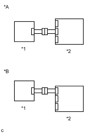
Text in Illustration *A w/o Rear Pretensioner *B w/ Rear Pretensioner *1 Seat Position Airbag Sensor *2 Airbag Sensor Assembly Connect the connectors to the airbag sensor assembly and seat position airbag sensor.
-
Connect the cable to the negative (-) auxiliary battery terminal.
-
Turn the power switch on (IG), and wait for at least 60 seconds.
-
Clear the DTCs stored in memory Click here.
-
Turn the power switch off.
-
Turn the power switch on (IG), and wait for at least 60 seconds.
-
Check for DTCs Click here.
OK DTC B1653/35 is not output. Tech Tips
Codes other than DTC B1653/35 may be output at this time, but they are not related to this check.
NG
CHECK SEAT POSITION AIRBAG SENSOR Click here
OK 
USE SIMULATION METHOD TO CHECK Click here
-
-
CHECK SEAT POSITION AIRBAG SENSOR
-
Text in Illustration *A w/o Rear Pretensioner *B w/ Rear Pretensioner *1 Seat Position Airbag Sensor *2 Airbag Sensor Assembly Turn the power switch off.
-
Disconnect the cable from the negative (-) auxiliary battery terminal.
CAUTION:
Wait at least 90 seconds after disconnecting the cable from the negative (-) auxiliary battery terminal to disable the SRS system.
-
Replace the seat position airbag sensor with a known good one Click here.
Tech Tips
Perform the following inspection using known good parts from another vehicle if possible.
-
Connect the cable to the negative (-) auxiliary battery terminal.
-
Turn the power switch on (IG), and wait for at least 60 seconds.
-
Clear the DTCs stored in memory Click here.
-
Turn the power switch off.
-
Turn the power switch on (IG), and wait for at least 60 seconds.
-
Check for DTCs Click here.
OK DTC B1653/35 is not output. Tech Tips
Codes other than DTC B1653/35 may be output at this time, but they are not related to this check.
-
Turn the power switch off.
-
Disconnect the cable from the negative (-) auxiliary battery terminal.
CAUTION:
Wait at least 90 seconds after disconnecting the cable from the negative (-) auxiliary battery terminal to disable the SRS system.
-
Restore the seat position airbag sensor that was installed for testing to its original location Click here.
NG
REPLACE AIRBAG SENSOR ASSEMBLY Click here
OK
REPLACE SEAT POSITION AIRBAG SENSOR Click here
-
-
CHECK FLOOR WIRE (OPEN)
-
w/o Rear Pretensioner
-
Disconnect the floor wire from the front seat inner belt assembly LH.
Tech Tips
SST has already been inserted into connector B.
-
Measure the resistance according to the value(s) in the table below.
Standard Resistance Tester Connection Condition Specified Condition P3-4 (LSP+) - P3-3 (LSP-) Always Below 1 Ω Result Result Proceed to NG A OK (for Manual seat) B OK (for Power seat) C -
Disconnect SST from connector B.
Text in Illustration *1 Seat Position Airbag Sensor *2 Airbag Sensor Assembly *3 Front Seat Inner Belt Assembly LH *4 Floor Wire *5 Connector B *6 Connector C *a Front view of wire harness connector
(to Airbag Sensor Assembly)
*b Front view of wire harness connector
(to Front Seat Inner Belt Assembly LH)
-
-
w/ Rear Pretensioner
-
Disconnect the floor wire from the front seat inner belt assembly LH.
Tech Tips
SST has already been inserted into connector B.
-
Measure the resistance according to the value(s) in the table below.
Standard Resistance Tester Connection Condition Specified Condition P3-4 (LSP+) - P3-3 (LSP-) Always Below 1 Ω Result Result Proceed to NG A OK (for Manual seat) B OK (for Power seat) C -
Disconnect SST from connector B.
Text in Illustration *1 Seat Position Airbag Sensor *2 Airbag Sensor Assembly *3 Front Seat Inner Belt Assembly LH *4 Floor Wire *5 Connector B *6 Connector C *a Front view of wire harness connector
(to Airbag Sensor Assembly)
*b Front view of wire harness connector
(to Front Seat Inner Belt Assembly LH)
-
B
REPLACE FRONT SEAT INNER BELT ASSEMBLY LH Click here
C
REPLACE FRONT SEAT INNER BELT ASSEMBLY LH Click here
A
REPLACE FLOOR WIRE
-
-
CHECK FLOOR WIRE (SHORT)
-
Text in Illustration *1 Seat Position Airbag Sensor *2 Airbag Sensor Assembly *3 Front Seat Inner Belt Assembly LH *4 Floor Wire *5 Connector C *a Front view of wire harness connector
(to Front Seat Inner Belt Assembly LH)
w/o Rear Pretensioner
-
Disconnect the floor wire from the front seat inner belt assembly LH.
-
Measure the resistance according to the value(s) in the table below.
Standard Resistance Tester Connection Condition Specified Condition P3-4 (LSP+) - P3-3 (LSP-) Always 1 MΩ or higher Result Result Proceed to NG A OK (for Manual seat) B OK (for Power seat) C
-
-
Text in Illustration *1 Seat Position Airbag Sensor *2 Airbag Sensor Assembly *3 Front Seat Inner Belt Assembly LH *4 Floor Wire *5 Connector C *a Front view of wire harness connector
(to Front Seat Inner Belt Assembly LH)
w/ Rear Pretensioner
-
Disconnect the floor wire from the front seat inner belt assembly LH.
-
Measure the resistance according to the value(s) in the table below.
Standard Resistance Tester Connection Condition Specified Condition P3-4 (LSP+) - P3-3 (LSP-) Always 1 MΩ or higher Result Result Proceed to NG A OK (for Manual seat) B OK (for Power seat) C
-
B
REPLACE FRONT SEAT INNER BELT ASSEMBLY LH Click here
C
REPLACE FRONT SEAT INNER BELT ASSEMBLY LH Click here
A
REPLACE FLOOR WIRE
-
-
CHECK FLOOR WIRE (SHORT TO B+)
-
Text in Illustration *1 Seat Position Airbag Sensor *2 Airbag Sensor Assembly *3 Front Seat Inner Belt Assembly LH *4 Floor Wire *5 Connector C *a Front view of wire harness connector
(to Front Seat Inner Belt Assembly LH)
w/o Rear Pretensioner
-
Turn the power switch off.
-
Disconnect the cable from the negative (-) auxiliary battery terminal.
CAUTION:
Wait at least 90 seconds after disconnecting the cable from the negative (-) auxiliary battery terminal to disable the SRS system.
-
Disconnect the floor wire from the front seat inner belt assembly LH.
-
Connect the cable to the negative (-) auxiliary battery terminal.
-
Turn the power switch on (IG).
-
Measure the voltage according to the value(s) in the table below.
Standard Voltage Tester Connection Switch Condition Specified Condition P3-4 (LSP+) - Body ground Power switch on (IG) Below 1 V P3-3 (LSP-) - Body ground Power switch on (IG) Below 1 V Result Result Proceed to NG A OK (for Manual seat) B OK (for Power seat) C
-
-
Text in Illustration *1 Seat Position Airbag Sensor *2 Airbag Sensor Assembly *3 Front Seat Inner Belt Assembly LH *4 Floor Wire *5 Connector C *a Front view of wire harness connector
(to Front Seat Inner Belt Assembly LH)
w/ Rear Pretensioner
-
Turn the power switch off.
-
Disconnect the cable from the negative (-) auxiliary battery terminal.
CAUTION:
Wait at least 90 seconds after disconnecting the cable from the negative (-) auxiliary battery terminal to disable the SRS system.
-
Disconnect the floor wire from the front seat inner belt assembly LH.
-
Connect the cable to the negative (-) auxiliary battery terminal.
-
Turn the power switch on (IG).
-
Measure the voltage according to the value(s) in the table below.
Standard Voltage Tester Connection Switch Condition Specified Condition P3-4 (LSP+) - Body ground Power switch on (IG) Below 1 V P3-3 (LSP-) - Body ground Power switch on (IG) Below 1 V Result Result Proceed to NG A OK (for Manual seat) B OK (for Power seat) C
-
B
REPLACE FRONT SEAT INNER BELT ASSEMBLY LH Click here
C
REPLACE FRONT SEAT INNER BELT ASSEMBLY LH Click here
A
REPLACE FLOOR WIRE
-
-
CHECK FLOOR WIRE (SHORT TO GROUND)
-
Text in Illustration *1 Seat Position Airbag Sensor *2 Airbag Sensor Assembly *3 Front Seat Inner Belt Assembly LH *4 Floor Wire *5 Connector C *a Front view of wire harness connector
(to Front Seat Inner Belt Assembly LH)
w/o Rear Pretensioner
-
Disconnect the floor wire from the front seat inner belt assembly LH.
-
Measure the resistance according to the value(s) in the table below.
Standard Resistance Tester Connection Condition Specified Condition P3-4 (LSP+) - Body ground Always 1 MΩ or higher P3-3 (LSP-) - Body ground Always 1 MΩ or higher Result Result Proceed to NG A OK (for Manual seat) B OK (for Power seat) C
-
-
Text in Illustration *1 Seat Position Airbag Sensor *2 Airbag Sensor Assembly *3 Front Seat Inner Belt Assembly LH *4 Floor Wire *5 Connector C *a Front view of wire harness connector
(to Front Seat Inner Belt Assembly LH)
w/ Rear Pretensioner
-
Disconnect the floor wire from the front seat inner belt assembly LH.
-
Measure the resistance according to the value(s) in the table below.
Standard Resistance Tester Connection Condition Specified Condition P3-4 (LSP+) - Body ground Always 1 MΩ or higher P3-3 (LSP-) - Body ground Always 1 MΩ or higher Result Result Proceed to NG A OK (for Manual seat) B OK (for Power seat) C
-
B
REPLACE FRONT SEAT INNER BELT ASSEMBLY LH Click here
C
REPLACE FRONT SEAT INNER BELT ASSEMBLY LH Click here
A
REPLACE FLOOR WIRE
-
-
CHECK CONNECTORS
-
Turn the power switch off.
-
Disconnect the cable from the negative (-) auxiliary battery terminal.
CAUTION:
Wait at least 90 seconds after disconnecting the cable from the negative (-) auxiliary battery terminal to disable the SRS system.
-
Check that the connectors are properly connected to the airbag sensor assembly, front seat inner belt assembly RH and seat position airbag sensor.
OK The connectors are properly connected. Tech Tips
If the connectors are not connected securely, reconnect the connectors and proceed to the next inspection.
-
Disconnect the connectors from the airbag sensor assembly, front seat inner belt assembly RH and seat position airbag sensor.
-
Check that the terminals of the connectors are not damaged.
OK The terminals are not deformed or damaged.
NG
REPLACE WIRE HARNESS
OK
-
-
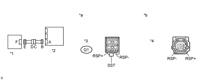
CHECK SEAT POSITION AIRBAG SENSOR CIRCUIT (OPEN)
-
Connect the connectors to the front seat inner belt assembly RH and No. 2 floor wire.
-
Using SST, connect terminals 12 (RSP+) and 13 (RSP-) of connector B.
Note
Do not forcibly insert SST into the terminals of the connector when connecting the wire.
- SST
- 09843-18040
-
Measure the resistance according to the value(s) in the table below.
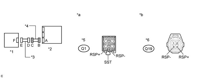
Standard Resistance Tester Connection Condition Specified Condition 2 (RSP+) - 1 (RSP-) Always Below 1 Ω Text in Illustration *1 Seat Position Airbag Sensor *2 Airbag Sensor Assembly *3 Connector B *4 Connector E *a Front view of wire harness connector
(to Airbag Sensor Assembly)
*b Front view of wire harness connector
(to Seat Position Airbag Sensor)
NG
CHECK NO. 2 FLOOR WIRE (OPEN) Click here
OK
-
-
CHECK SEAT POSITION AIRBAG SENSOR CIRCUIT (SHORT)
-
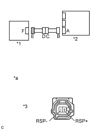
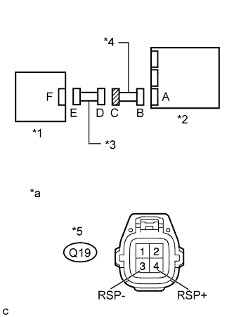
Text in Illustration *1 Seat Position Airbag Sensor *2 Airbag Sensor Assembly *3 Connector E *a Front view of wire harness connector
(to Seat Position Airbag Sensor)
Disconnect SST from connector B.
-
Measure the resistance according to the value(s) in the table below.
Standard Resistance Tester Connection Condition Specified Condition 2 (RSP+) - 1 (RSP-) Always 1 MΩ or higher
NG
CHECK NO. 2 FLOOR WIRE (SHORT) Click here
OK
-
-
CHECK SEAT POSITION AIRBAG SENSOR CIRCUIT (SHORT TO B+)
-
Text in Illustration *1 Seat Position Airbag Sensor *2 Airbag Sensor Assembly *3 Connector E *a Front view of wire harness connector
(to Seat Position Airbag Sensor)
Connect the cable to the negative (-) auxiliary battery terminal.
-
Turn the power switch on (IG).
-
Measure the voltage according to the value(s) in the table below.
Standard Voltage Tester Connection Switch Condition Specified Condition 2 (RSP+) - Body ground Power switch on (IG) Below 1 V 1 (RSP-) - Body ground Power switch on (IG) Below 1 V
NG
CHECK NO. 2 FLOOR WIRE (SHORT TO B+) Click here
OK
-
-
CHECK SEAT POSITION AIRBAG SENSOR CIRCUIT (SHORT TO GROUND)
-
Text in Illustration *1 Seat Position Airbag Sensor *2 Airbag Sensor Assembly *3 Connector E *a Front view of wire harness connector
(to Seat Position Airbag Sensor)
Turn the power switch off.
-
Disconnect the cable from the negative (-) auxiliary battery terminal.
CAUTION:
Wait at least 90 seconds after disconnecting the cable from the negative (-) auxiliary battery terminal to disable the SRS system.
-
Measure the resistance according to the value(s) in the table below.
Standard Resistance Tester Connection Condition Specified Condition 2 (RSP+) - Body ground Always 1 MΩ or higher 1 (RSP-) - Body ground Always 1 MΩ or higher
NG
CHECK NO. 2 FLOOR WIRE (SHORT TO GROUND) Click here
OK
-
-
CHECK DTC
-
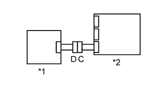
Text in Illustration *1 Seat Position Airbag Sensor *2 Airbag Sensor Assembly Connect the connectors to the airbag sensor assembly and seat position airbag sensor.
-
Connect the cable to the negative (-) auxiliary battery terminal.
-
Turn the power switch on (IG), and wait for at least 60 seconds.
-
Clear the DTCs stored in memory Click here.
-
Turn the power switch off.
-
Turn the power switch on (IG), and wait for at least 60 seconds.
-
Check for DTCs Click here.
OK DTC B1653/35 is not output. Tech Tips
Codes other than DTC B1653/35 may be output at this time, but they are not related to this check.
NG
CHECK SEAT POSITION AIRBAG SENSOR Click here
OK
USE SIMULATION METHOD TO CHECK Click here
-
-
CHECK SEAT POSITION AIRBAG SENSOR
-
Text in Illustration *1 Seat Position Airbag Sensor *2 Airbag Sensor Assembly Turn the power switch off.
-
Disconnect the cable from the negative (-) auxiliary battery terminal.
CAUTION:
Wait at least 90 seconds after disconnecting the cable from the negative (-) auxiliary battery terminal to disable the SRS system.
-
Replace the seat position airbag sensor with a known good one Click here.
Tech Tips
Perform the following inspection using known good parts from another vehicle if possible.
-
Connect the cable to the negative (-) auxiliary battery terminal.
-
Turn the power switch on (IG), and wait for at least 60 seconds.
-
Clear the DTCs stored in memory Click here.
-
Turn the power switch off.
-
Turn the power switch on (IG), and wait for at least 60 seconds.
-
Check for DTCs Click here.
OK DTC B1653/35 is not output. Tech Tips
Codes other than DTC B1653/35 may be output at this time, but they are not related to this check.
-
Turn the power switch off.
-
Disconnect the cable from the negative (-) auxiliary battery terminal.
CAUTION:
Wait at least 90 seconds after disconnecting the cable from the negative (-) auxiliary battery terminal to disable the SRS system.
-
Restore the seat position airbag sensor that was installed for testing to its original location Click here.
NG
REPLACE AIRBAG SENSOR ASSEMBLY Click here
OK
REPLACE SEAT POSITION AIRBAG SENSOR Click here
-
-
CHECK NO. 2 FLOOR WIRE (OPEN)
-
Disconnect the No. 2 floor wire from the front seat inner belt assembly RH.
Tech Tips
SST has already been inserted into connector B.
-
Measure the resistance according to the value(s) in the table below.
Standard Resistance Tester Connection Condition Specified Condition Q19-4 (RSP+) - Q19-3 (RSP-) Always Below 1 Ω Result Result Proceed to NG A OK (for Manual seat) B OK (for Power seat) C -
Disconnect SST from connector B.
Text in Illustration *1 Seat Position Airbag Sensor *2 Airbag Sensor Assembly *3 Front Seat Inner Belt Assembly RH *4 No. 2 Floor Wire *5 Connector B *6 Connector C *a Front view of wire harness connector
(to Airbag Sensor Assembly)
*b Front view of wire harness connector
(to Front Seat Inner Belt Assembly RH)
B
REPLACE FRONT SEAT INNER BELT ASSEMBLY RH Click here
C
REPLACE FRONT SEAT INNER BELT ASSEMBLY RH Click here
A
REPLACE NO. 2 FLOOR WIRE
-
-
CHECK NO. 2 FLOOR WIRE (SHORT)
-
Text in Illustration *1 Seat Position Airbag Sensor *2 Airbag Sensor Assembly *3 Front Seat Inner Belt Assembly RH *4 No. 2 Floor Wire *5 Connector C *a Front view of wire harness connector
(to Front Seat Inner Belt Assembly RH)
Disconnect the No. 2 floor wire from the front seat inner belt assembly RH.
-
Measure the resistance according to the value(s) in the table below.
Standard Resistance Tester Connection Condition Specified Condition Q19-4 (RSP+) - Q19-3 (RSP-) Always 1 MΩ or higher Result Result Proceed to NG A OK (for Manual seat) B OK (for Power seat) C
B
REPLACE FRONT SEAT INNER BELT ASSEMBLY RH Click here
C
REPLACE FRONT SEAT INNER BELT ASSEMBLY RH Click here
A
REPLACE NO. 2 FLOOR WIRE
-
-
CHECK NO. 2 FLOOR WIRE (SHORT TO B+)
-
Text in Illustration *1 Seat Position Airbag Sensor *2 Airbag Sensor Assembly *3 Front Seat Inner Belt Assembly RH *4 No. 2 Floor Wire *5 Connector C *a Front view of wire harness connector
(to Front Seat Inner Belt Assembly RH)
Turn the power switch off.
-
Disconnect the cable from the negative (-) auxiliary battery terminal.
CAUTION:
Wait at least 90 seconds after disconnecting the cable from the negative (-) auxiliary battery terminal to disable the SRS system.
-
Disconnect the No. 2 floor wire from the front seat inner belt assembly RH.
-
Connect the cable to the negative (-) auxiliary battery terminal.
-
Turn the power switch on (IG).
-
Measure the voltage according to the value(s) in the table below.
Standard Voltage Tester Connection Switch Condition Specified Condition Q19-4 (RSP+) - Body ground Power switch on (IG) Below 1 V Q19-3 (RSP-) - Body ground Power switch on (IG) Below 1 V Result Result Proceed to NG A OK (for Manual seat) B OK (for Power seat) C
B
REPLACE FRONT SEAT INNER BELT ASSEMBLY RH Click here
C
REPLACE FRONT SEAT INNER BELT ASSEMBLY RH Click here
A
REPLACE NO. 2 FLOOR WIRE
-
-
CHECK NO. 2 FLOOR WIRE (SHORT TO GROUND)
-
Text in Illustration *1 Seat Position Airbag Sensor *2 Airbag Sensor Assembly *3 Front Seat Inner Belt Assembly RH *4 No. 2 Floor Wire *5 Connector C *a Front view of wire harness connector
(to Front Seat Inner Belt Assembly RH)
Disconnect the No. 2 floor wire from the front seat inner belt assembly RH.
-
Measure the resistance according to the value(s) in the table below.
Standard Resistance Tester Connection Condition Specified Condition Q19-4 (RSP+) - Body ground Always 1 MΩ or higher Q19-3 (RSP-) - Body ground Always 1 MΩ or higher Result Result Proceed to NG A OK (for Manual seat) B OK (for Power seat) C
B
REPLACE FRONT SEAT INNER BELT ASSEMBLY RH Click here
C
REPLACE FRONT SEAT INNER BELT ASSEMBLY RH Click here
A
REPLACE NO. 2 FLOOR WIRE
-