- Click here
PRECAUTION
CAUTION:Be sure to read Precaution thoroughly before servicing (Click here).
Note:After turning the power switch off, waiting time may be required before disconnecting the cable from the negative (-) auxiliary battery terminal. Therefore, make sure to read the disconnecting the cable from the negative (-) auxiliary battery terminal notices before proceeding with work (Click here).
- Click here
REMOVE REAR NO. 2 FLOOR BOARD
-
Remove the rear No. 2 floor board.
-
- Click here
REMOVE REAR DECK FLOOR BOX
-
Remove the rear deck floor box.
-
- Click here
REMOVE REAR NO. 3 FLOOR BOARD
-
Remove the rear No. 3 floor board.
-
- Click here
REMOVE DECK FLOOR BOX RH
-
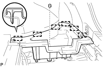
Remove the clip.
-
Disengage the 6 guides and remove the deck floor box RH.
-
- Click here
REMOVE REAR FLOOR BOARD UPPER NO. 3 PLATE
-
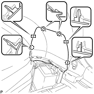
Disengage the 4 claws and 2 guides, and remove the rear floor board upper No. 3 plate.
-
- Click here
DISCONNECT CABLE FROM AUXILIARY BATTERY TERMINAL
CAUTION:Wait at least 90 seconds after disconnecting the cable from the negative (-) auxiliary battery terminal to disable the SRS system.
Note:When disconnecting the cable, some systems need to be initialized after the cable is reconnected (Click here).
- Click here
REMOVE LOWER NO. 3 STEERING WHEEL COVER
-
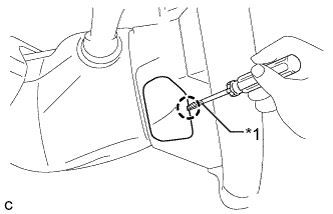
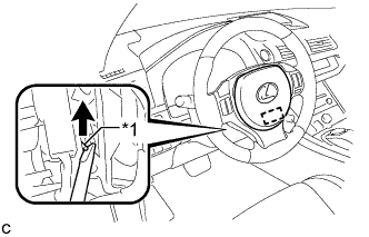
Using a screwdriver with its tip wrapped with protective tape, disengage the claw to remove the lower No. 3 steering wheel cover.
Table 1. Text in Illustration *1 Protective Tape
-
- Click here
REMOVE LOWER NO. 2 STEERING WHEEL COVER
-
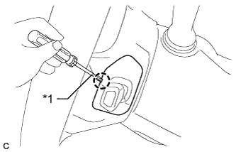
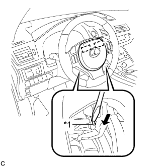
Using a screwdriver with its tip wrapped with protective tape, disengage the claw to remove the lower No. 2 steering wheel cover.
Table 2. Text in Illustration *1 Protective Tape
-
- Click here
REMOVE HORN BUTTON ASSEMBLY
CAUTION:When storing the horn button assembly, keep the airbag deployment side facing upward.
-
Check that the power switch is off.
-
Check that the cable is disconnected from the negative (-) auxiliary battery terminal.
CAUTION:Wait at least 90 seconds after disconnecting the cable from the negative (-) auxiliary battery terminal to disable the SRS system.
-
Using a screwdriver, push up the torsion spring to disengage the pin.
Table 3. Text in Illustration *1 Torsion Spring Tip:Insert the screwdriver from the installation hole of the lower No. 3 steering wheel cover.
-
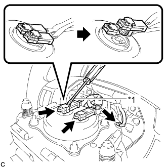
Using a screwdriver, push in the torsion springs to disengage the 2 pins.
Table 4. Text in Illustration *1 Torsion Spring Note:Do not drop the horn button assembly.
Tip:Insert the screwdriver from the installation holes in the lower No. 3 steering wheel cover and lower No. 2 steering wheel cover.
-
Pull out the horn button assembly from the steering wheel assembly and support the horn button assembly with one hand.
Note:When removing the horn button assembly, do not pull the airbag wire harness.
-
Disconnect the horn connector from the horn button assembly.
Table 5. Text in Illustration *1 Protective Tape -
Using a screwdriver with its tip wrapped with protective tape, release the 2 airbag connector locks.
-
Disconnect the 2 airbag connectors to remove the horn button assembly.
Note:When disconnecting any airbag connector, take care not to damage the airbag wire harness.
-