METER / GAUGE SYSTEM Malfunction in Water Temperature Warning Light
DESCRIPTION
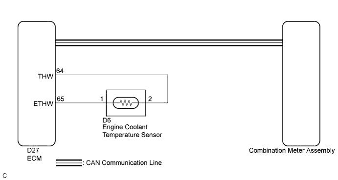
In this circuit, the meter ECU receives engine coolant temperature signals from the ECM using the CAN communication system. The meter ECU displays engine coolant temperature that is calculated based on the data received from the ECM.
WIRING DIAGRAM
INSPECTION PROCEDURE
Tech Tips
-
If there is an open or short in the engine coolant temperature sensor circuit, the ECM stores the DTCs. Troubleshoot the SFI System Click here.
-
If the exhaust heat recirculation system has a malfunction, the engine coolant temperature hot warning light comes on to inform the driver of the malfunction.
PROCEDURE
-
CHECK CAN COMMUNICATION SYSTEM
-
Check if a CAN communication DTC is output Click here.
Result Result Proceed to CAN communication DTC is not output. A CAN communication DTC is output. B
B 
GO TO CAN COMMUNICATION SYSTEM Click here
A 
-
-
SYSTEM CHECK
-
Check the water temperature warning light.
Result Result Proceed to Water temperature warning light does not come on. A Water temperature warning light remains on. B
B 
CHECK FOR DTC Click here
A
-
-
PERFORM ACTIVE TEST USING INTELLIGENT TESTER (COOLANT HOT INDICATOR)
-
Connect the intelligent tester to the DLC3.
-
Turn the power switch on (IG).
-
Turn the intelligent tester on.
-
Enter the following menus: Body / Combination Meter / Active Test.
-
Check the operation by referring to the table below.
Combination Meter Tester Display Test Part Control Range Diagnostic Note Coolant Hot Indicator Water temperature warning light OFF or ON - OK Water temperature warning light operation is normal.
NG
REPLACE COMBINATION METER ASSEMBLY Click here
OK
-
-
CHECK FOR DTC
-
Check for the DTC.
Result Result Proceed to No DTC is output. A DTC P0115 is output. B DTC B1503 is output. C
B
GO TO SFI SYSTEM Click here
C
GO TO METER / GAUGE SYSTEM Click here
A
-
-
READ VALUE USING INTELLIGENT TESTER (COOLANT TEMPERATURE, COOLANT TEMP)
-
Connect the intelligent tester to the DLC3.
-
Turn the power switch on (IG).
-
Turn the intelligent tester on.
-
Enter the following menus:
-
for Combination Meter: Body / Combination Meter / Data List.
-
for Engine: Powertrain / Engine and ECT / Data List.
-
-
Check the values by referring to the table below.
Combination Meter Tester Display Measurement Item/Range Normal Condition Diagnostic Note Coolant Temperature Engine coolant temperature/-40 to 127.5°C (-40 to 261.5°F) After warming up: 75 to 100°C (167 to 212°F) - -
Check the values by referring to the table below.
Engine and ECT Tester Display Measurement Item/Range Normal Condition Diagnostic Note Coolant Temp Engine coolant temperature/Min.: -40°C (-40°F), Max.: 140°C (284°F) After warming up: 75 to 100°C (167 to 212°F)
-
After warming up the engine: the engine coolant temperature 75 to 100°C (167 to 212°F).
-
If the value is -40°C (-40°F) or 140°C (284°F), the sensor circuit open or shorted.
Note
Enter the inspection mode Click here.
Result Result Proceed to The data list values of the ECUs do not match. OK The data list values of the ECUs match. NG Tech Tips
When the Data List values of the ECUs do not match, a signal output error of the ECM is suspected.
-
NG
GO TO SFI SYSTEM Click here
OK
-
-
REPLACE COMBINATION METER ASSEMBLY
-
Replace the combination meter assembly with a new or a known good one Click here.
OK The operation of the water temperature warning light returns to normal.
NG
REPLACE ECM Click here
OK 
END
-