METER / GAUGE SYSTEM TERMINALS OF ECU
-
COMBINATION METER ASSEMBLY

-
Measure the voltage and resistance according to the value(s) in the table below.
Terminal No. (Symbol) Wiring Color Terminal Description Condition Specified Condition H19-3 (LVWG)*1 - Body ground L - Body ground Headlight leveling signal Power switch on (IG), leveling indicator light off 11 to 14 V Power switch on (IG), leveling indicator light on Below 1 V H19-4 (RRSB)*2 or *3 - Body ground R - Body ground Rear seat belt buckle switch RH signal Power switch on (IG), rear seat belt buckle switch RH unfastened Below 1 V Power switch on (IG), rear seat belt buckle switch RH fastened 11 to 14 V H19-5 (RCSB)*2 or *3 - Body ground L - Body ground Rear seat belt buckle switch center signal Power switch on (IG), rear seat belt buckle switch center unfastened Below 1 V Power switch on (IG), rear seat belt buckle switch center fastened 11 to 14 V H19-6 (RLSB)*2 or *3 - Body ground B - Body ground Rear seat belt buckle switch LH signal Power switch on (IG), rear seat belt buckle switch LH unfastened Below 1 V Power switch on (IG), rear seat belt buckle switch LH fastened 11 to 14 V H19-7 (WLVL) - Body ground LG - Body ground Washer level warning light signal Power switch on (IG), washer warning light off 4 to 6 V Power switch on (IG), washer warning light on Below 1 V H19-8 (S) - Body ground G - Body ground Oil pressure signal Power switch on (IG), oil pressure warning light off 4 to 6 V Power switch on (IG), washer warning light on Below 1 V H19-9 (E2) - Body ground W-B - Body ground Ground Always Below 1 Ω H19-10 (ILL-) - Body ground B - Body ground Illumination signal Power switch on (IG), light control switch in tail or head position Pulse generation H19-11 (ECOD) - Body ground P - Body ground Combination switch assembly signal Power switch on (IG), combination switch assembly not operated 11 to 14 V Power switch on (IG), combination switch assembly turns counterclockwise (on ECO position) Below 1 V H19-12 (IMAN) - Body ground R - Body ground Combination switch assembly signal Power switch on (IG), combination switch assembly not operated 11 to 14 V Power switch on (IG), combination switch assembly turns clockwise (on SPORT position) Below 1 V H19-13 (ACIN) - Body ground L - Body ground Rear passenger seat condition signal Power switch on (IG), rear passenger seat not occupied Below 1 V Power switch on (IG), any of rear passenger seat occupied 4 to 6 V H19-14 (REV) - Body ground G - Body ground Light control rheostat signal Power switch on (IG), light control rheostat turns fully upwards (MAX.) 8 kΩ or higher Power switch on (IG), light control rheostat position between (MIN.) and (MAX.) 50 to 8 kΩ Power switch on (IG), light control rheostat turns fully downwards (MIN.) Below 50 Ω H19-15 (TC) - H19-16 (SW1) L - SB Tail cancel signal Power switch on (IG), light control rheostat turns fully upwards (MAX.) 8 kΩ or higher Power switch on (IG), light control rheostat position except above Below 8 kΩ H19-16 (SW1) - Body ground SB - Body ground Light control rheostat signal Always 4 to 6 V H19-19 (STRG) - Body ground P - Body ground DISP switch (Steering pad switch assembly) signal Power switch on (IG), DISP switch not pressed 4 to 6 V Power switch on (IG), DISP switch pressed Below 1 V H19-21 (IG2) - Body ground BR - Body ground Power switch signal Power switch off Below 1 V Power switch on (IG) 11 to 14 V H19-22 (B) - Body ground V - Body ground Auxiliary battery Power switch off 11 to 14 V H19-23 (B) - Body ground G - Body ground Turn indicator light signal Power switch on (IG), turn signal RH indicator light off Below 1 V Power switch on (IG), turn signal RH indicator light blinking Below 1 V ←→ 11 to 14 V H19-24 (B) - Body ground Y - Body ground Turn indicator light signal Power switch on (IG), turn signal LH indicator light off Below 1 V Power switch on (IG), turn signal LH indicator light blinking Below 1 V ←→ 11 to 14 V H19-26 (TWS3) - H19-9 (E2) GR - W-B Engine coolant temperature sensor signal Power switch on (IG), coolant temperature below 113°C (235°F) 0.2 to 4.8 V Power switch on (IG), coolant temperature below 120°C (248°F) Below 0.15 V H19-27 (L) - H19-30 (FE) SB - P Fuel signal Power switch on (IG), fuel level not low 4 to 14 V Power switch on (IG), fuel level low 4 V or less H19-28 (EFI) - Body ground R - Body ground MIL (Check engine warning light) signal Power switch on (IG), MIL off 11 to 14 V Power switch on (IG), MIL on Below 1 V H19-29 (P/SB) - Body ground B - Body ground Front passenger side seat belt buckle switch signal, front passenger seat condition signal Power switch on (IG), sit on the front passenger seat, and front passenger side seat belt unfastened Below 1 V Power switch on (IG), sit on the front passenger seat, and front passenger side seat belt fastened 11 to 14 V H19-31 (CANL) - Body ground V - Body ground CAN communication line - - H19-32 (CANH) - Body ground P - Body ground CAN communication line - - H19-33 (EP) - Body Ground W-B - Body ground Ground Always Below 1 Ω H19-34 (E2) - Body Ground G - Body ground Ground Always Below 1 Ω H19-36 (SW3) - Body ground W - Body ground Ground Always Below 1 Ω H19-39 (SI) - Body ground V - Body ground Speed signal for other system (Input) Power switch on (IG), turn the wheel slowly. Pulse generation
(See waveform 1)
H19-40 (+S) - Body ground V - Body ground Speed signal for other system (Output) Power switch on (IG), turn the wheel slowly. Pulse generation
(See waveform 1)
-
*1: w/ Automatic Type Headlight Beam Level Control
-
*2: w/ Seat Heater
-
*3: w/ Rear Seat Belt Warning
-
-
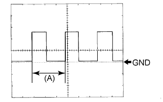
Waveform 1 (Reference): Using an oscilloscope:
Item Condition Tool setting 5 V/DIV., 20 ms/DIV. Vehicle condition Wheel being rotated Tech Tips
When the system is functioning normally, one wheel revolution generates 4 pulses. As the vehicle speed increases, the width indicated by (A) in the illustration narrows.
-
-
COMBINATION METER ASSEMBLY INNER CIRCUIT
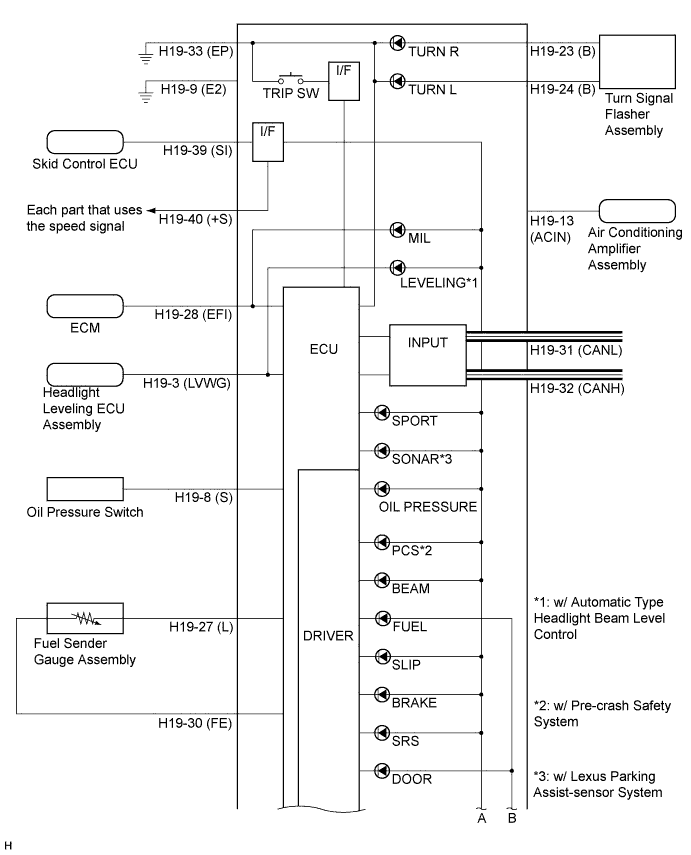
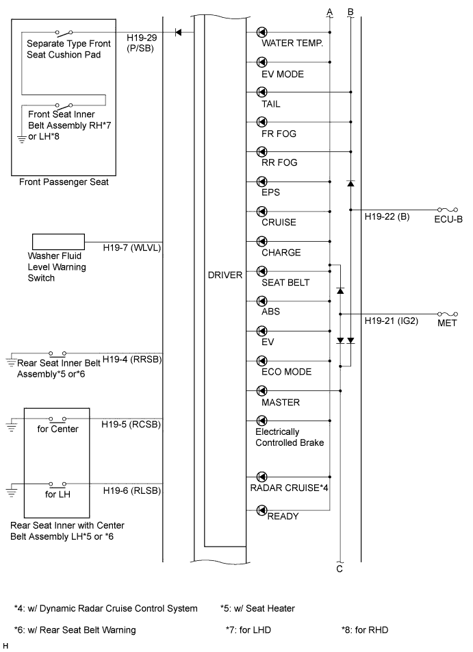
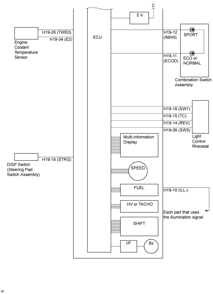
Terminal No. Wire Harness Side H19 1 - 2 - 3 (LVWG) Headlight leveling ECU assembly*1 4 (RRSB) Rear seat inner belt assembly RH*5 or *6 5 (RCSB) Rear seat inner with center belt assembly LH (for Center)*5 or *6 6 (RLSB) Rear seat inner with center belt assembly LH (for LH)*5 or *6 7 (WLVL) Washer fluid level warning switch 8 (S) Oil pressure switch 9 (E2) Ground 10 (ILL-) Each part that uses the illumination signal 11 (ECOD) Combination switch assembly 12 (IMAN) Combination switch assembly 13 (ACIN) Air conditioning amplifier assembly 14 (REV) Light control rheostat 15 (TC) Light control rheostat 16 (SW1) Light control rheostat 17 - 18 - 19 (STRG) DISP switch (Steering pad switch assembly) 20 - 21(IG2) MET 22 (B) ECU-B Fuse 23 (B) Turn signal flasher assembly 24 (B) Turn signal flasher assembly 25 - 26 (TWS3) Engine coolant temperature sensor 27 (L) Fuel sender gauge assembly 28 (EFI) ECM 29 (P/SB) Separate type front seat cushion pad, front seat inner belt assembly RH*7 or LH*8 30 (FE) Fuel sender gauge assembly 31(CANL) CAN communication line 32 (CANH) CAN communication line 33 (EP) Ground 34 (E2) Engine coolant temperature Sensor 35 - 36 (SW3) Light control rheostat 37 - 38 - 39 (SI) Skid control ECU 40 (+S) Each Part that uses the Speed Signal
-
*1: w/ Automatic Type Headlight Beam Level Control
-
*5: w/ Seat Heater
-
*6: w/ Rear Seat Belt Warning
-
*7: for LHD
-
*8: for RHD
-