ENGINE IMMOBILISER SYSTEM Security Indicator Light Does not Blink
DESCRIPTION
-
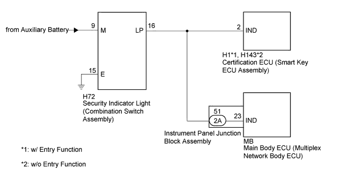
The certification ECU (smart key ECU assembly) blinks the security indicator light when the immobiliser is set (the power switch is off).
WIRING DIAGRAM
INSPECTION PROCEDURE
Note
-
Inspect the fuses for circuits related to this system before performing the following inspection procedure.
-
Before replacing the certification ECU (smart key ECU assembly), refer to the Service Bulletin.
PROCEDURE
-
PERFORM ACTIVE TEST USING INTELLIGENT TESTER (SECURITY INDICATOR LIGHT)
-
Connect the intelligent tester to the DLC3.
-
Turn the power switch on (IG).
-
Turn the intelligent tester on.
-
Enter the following menus: Body / Entry&Start / Active Test.
-
Perform the Active Test according to the display on the intelligent tester.
Entry&Start (Certification ECU (Smart Key ECU Assembly)) Tester Display Test Part Control Range Diagnostic Note Immobiliser Indicator Security indicator light ON/OFF The test is possible when the following conditions are met:
-
The key is in the cabin.
-
The power switch is on (IG).
-
-
Enter the following menus: Body / Main Body / Active Test.
-
Perform the Active Test according to the display on the intelligent tester.
Main Body (Main Body ECU (Multiplex Network Body ECU)) Tester Display Test Part Control Range Diagnostic Note Security Indicator Security indicator light ON/OFF - Result Result Proceed to Security indicator light operation is normal performing the "Main Body" and "Entry&Start" Active Test A
-
Security indicator light operation is not normal performing the "Entry&Start" Active Test
-
Security indicator light operation is normal performing the "Main Body" Active Test
B
-
Security indicator light operation is normal performing the "Entry&Start" Active Test
-
Security indicator light operation is not normal performing the "Main Body" Active Test
C Security indicator light operation is not normal performing the "Main Body" and "Entry&Start" Active Test D -
B 
CHECK HARNESS AND CONNECTOR (SECURITY INDICATOR LIGHT - CERTIFICATION ECU) Click here
C
CHECK HARNESS AND CONNECTOR (SECURITY INDICATOR LIGHT - INSTRUMENT PANEL JUNCTION BLOCK) Click here
D
CHECK HARNESS AND CONNECTOR Click here
A 
USE SIMULATION METHOD TO CHECK Click here
-
-
CHECK HARNESS AND CONNECTOR (SECURITY INDICATOR LIGHT - CERTIFICATION ECU)
-
Disconnect the H72 indicator light connector.
-
Disconnect the H1*1 or H143*2 ECU connector.
-
*1: w/ Entry Function
-
*2: w/o Entry Function
-
-
Measure the resistance according to the value(s) in the table below.
Standard Resistance Tester Connection Condition Specified Condition H1-2 (IND) - H72-16 (LP)*1
H143-2 (IND) - H72-16 (LP)*2
Always Below 1 Ω H1-2 (IND) - Body ground*1
H143-2 (IND) - Body ground*2
Always 10 kΩ or higher
-
*1: w/ Entry Function
-
*2: w/o Entry Function
-
NG 
REPAIR OR REPLACE HARNESS OR CONNECTOR
OK
REPLACE CERTIFICATION ECU (SMART KEY ECU ASSEMBLY)
-
-
CHECK HARNESS AND CONNECTOR (SECURITY INDICATOR LIGHT - INSTRUMENT PANEL JUNCTION BLOCK)
-
Disconnect the H72 indicator light connector.
-
Disconnect the 2A junction block connector.
-
Measure the resistance according to the value(s) in the table below.
Standard Resistance Tester Connection Condition Specified Condition 2A-51 - H72-16 (LP) Always Below 1 Ω 2A-51 - Body ground Always 10 kΩ or higher
NG
REPAIR OR REPLACE HARNESS OR CONNECTOR
OK 
-
-
INSPECT INSTRUMENT PANEL JUNCTION BLOCK ASSEMBLY
-
Remove the main body ECU (multiplex network body ECU) Click here.
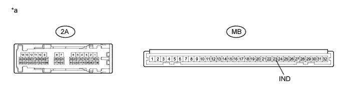
Text in Illustration *a Component without harness connected
(Instrument Panel Junction Block Assembly)
- - -
Disconnect the 2A junction block connector.
-
Measure the resistance according to the value(s) in the table below.
Standard Resistance Tester Connection Condition Specified Condition 2A-51 - MB-23 (IND) Always Below 1 Ω 2A-51 - Body ground Always 10 kΩ or higher
NG
REPLACE INSTRUMENT PANEL JUNCTION BLOCK ASSEMBLY Click here
OK
REPLACE MAIN BODY ECU (MULTIPLEX NETWORK BODY ECU) Click here
-
-
CHECK HARNESS AND CONNECTOR
-
Disconnect the H72 indicator light connector.
-
Disconnect the H1*1 or H143*2 ECU connector.
-
*1: w/ Entry Function
-
*2: w/o Entry Function
-
-
Disconnect the 2A junction block connector.
-
Measure the resistance according to the value(s) in the table below.
Standard Resistance Tester Connection Condition Specified Condition H1-2 (IND) - H72-16 (LP)*1
H143-2 (IND) - H72-16 (LP)*2
Always Below 1 Ω 2A-51 - H72-16 (LP) Always Below 1 Ω H72-16 (LP) - Body ground Always 10 kΩ or higher H72-15 (E) - Body ground Always Below 1 Ω
-
*1: w/ Entry Function
-
*2: w/o Entry Function
-
-
Measure the voltage according to the value(s) in the table below.
Standard Voltage Tester Connection Condition Specified Condition H72-9 (M) - Body ground Power switch off 11 to 14 V
NG
REPAIR OR REPLACE HARNESS OR CONNECTOR
OK
-
-
REPLACE SECURITY INDICATOR LIGHT (COMBINATION SWITCH ASSEMBLY)
-
Temporarily replace the security indicator light (combination switch assembly) with a new or known good one Click here.
-
When the immobiliser is set (the power switch is off), check that the security indicator light blinks.
OK Security indicator light blinks.
NG
REPLACE CERTIFICATION ECU (SMART KEY ECU ASSEMBLY) Click here
OK
END (SECURITY INDICATOR LIGHT WAS DEFECTIVE)
-
-
REPLACE CERTIFICATION ECU (SMART KEY ECU ASSEMBLY)
-
Temporarily replace the certification ECU (smart key ECU assembly) with a new or known good one.
-
When the immobiliser is set (the power switch is off), check that the security indicator light blinks.
OK Security indicator light blinks.
NG
REPLACE MAIN BODY ECU (MULTIPLEX NETWORK BODY ECU) Click here
OK
END (CERTIFICATION ECU (SMART KEY ECU ASSEMBLY) WAS DEFECTIVE)
-