ENGINE IMMOBILISER SYSTEM, Diagnostic DTC:B279A
| DTC Code | DTC Name |
|---|---|
| B279A | Theft Deterrent System Communication Line High Fixation |
DESCRIPTION
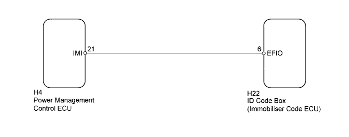
When the communication line (IMI - EFIO) between the power management control ECU and ID code box (immobiliser code ECU) is stuck high, the power management control ECU stores this DTC.
| DTC Code | DTC Detection Condition | Trouble Area | DTC Output Confirmation Operation |
|---|---|---|---|
| B279A | The communication line (IMI - EFIO) between the power management control ECU and ID code box (immobiliser code ECU) is stuck high (1 trip detection logic*1). |
|
Turn the power switch on (IG) and wait 6 seconds. |
-
*1: Only output while a malfunction is present.
-
*2: w/ Blocking System
| Vehicle Condition when Malfunction Detected | Fail-safe Operation when Malfunction Detected |
|---|---|
| Hybrid control system cannot be started | Hybrid control system cannot be started |
| DTC Code | Data List and Active Test |
|---|---|
| B279A | - |
WIRING DIAGRAM
-
w/o Blocking System
-
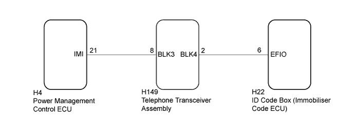
w/ Blocking System
INSPECTION PROCEDURE
Note
-
If the ID code box (immobiliser code ECU) is replaced, register the ECU code and ECU communication ID.
-
The fixed 12 V power source voltage in the power management control ECU is output through a resistance from terminal IMI. The ID code box (immobiliser code ECU) grounds or does not ground this power source voltage accordingly.
-
After performing repair, perform the operation that fulfills the DTC output confirmation operation, and then confirm that no DTCs are output again.
-
*: w/ Blocking System
Tech Tips
When DTC B279A and the certification ECU (smart key ECU assembly) DTC are output simultaneously, first perform troubleshooting for the certification ECU (smart key ECU assembly) DTC.
PROCEDURE
-
CLEAR DTC
-
Clear the DTCs Click here.
NEXT 
-
-
CHECK FOR DTC
-
Turn the power switch on (IG) and wait 10 seconds.
-
Check for DTCs Click here.
Result Result Proceed to DTC B279A is output A DTC B279A and other DTCs are output B Tech Tips
If DTCs other than DTC B279A are output, troubleshoot those DTCs first.
B 
GO TO DIAGNOSTIC TROUBLE CODE CHART Click here
A
-
-
CHECK CONNECTION OF CONNECTOR
-
Turn the power switch off.
-
Check that the connectors are properly connected to the power management control ECU and ID code box (immobiliser code ECU).
OK Connectors are properly connected.
NG
CONNECT CONNECTORS PROPERLY
OK
-
-
SYSTEM CHECK
-
Check the vehicle specification.
Result Result Proceed to w/o Blocking System A w/ Blocking System B
B 
CHECK HARNESS AND CONNECTOR (POWER MANAGEMENT CONTROL ECU - TELEPHONE TRANSCEIVER ASSEMBLY) Click here
A
-
-
CHECK HARNESS AND CONNECTOR (ID CODE BOX - POWER MANAGEMENT CONTROL ECU)
-
Disconnect the H22 ID code box (immobiliser code ECU) connector.
-
Disconnect the H4 power management control ECU connector.
-
Measure the resistance according to the value(s) in the table below.
Standard Resistance Tester Connection Condition Specified Condition H22-6 (EFIO) - H4-21 (IMI) Always Below 1 Ω H4-21 (IMI) - Body ground Always 10 kΩ or higher -
Measure the voltage according to the value(s) in the table below.
Standard Voltage Tester Connection Condition Specified Condition H4-21 (IMI) - Body ground Always Below 1 V
NG
REPAIR OR REPLACE HARNESS OR CONNECTOR
OK
-
-
REPLACE ID CODE BOX (IMMOBILISER CODE ECU)
-
Replace the ID code box (immobiliser code ECU) with a new one.
NEXT
-
-
CLEAR DTC
-
Clear the DTCs Click here.
NEXT
-
-
REGISTER RECOGNITION CODES
-
Register the recognition codes in the ECUs.
Tech Tips
Refer to the Service Bulletin.
NEXT
-
-
REGISTER ECU COMMUNICATION ID (ID CODE BOX - POWER MANAGEMENT CONTROL ECU)
-
Register the ECU communication ID.
Tech Tips
Refer to the Service Bulletin.
NEXT
-
-
CHECK FOR DTC
-
Check for DTCs Click here.
Tech Tips
Before checking for DTCs, perform the "DTC Output Confirmation Operation" procedure.
OK DTC B279A is not output.
NG
REPLACE POWER MANAGEMENT CONTROL ECU Click here
OK 
END (ID CODE BOX (IMMOBILISER CODE ECU) WAS DEFECTIVE)
-
-
CHECK HARNESS AND CONNECTOR (POWER MANAGEMENT CONTROL ECU - TELEPHONE TRANSCEIVER ASSEMBLY)
-
Disconnect the H149 telephone transceiver assembly connector.
-
Disconnect the H4 power management control ECU connector.
-
Measure the resistance according to the value(s) in the table below.
Standard Resistance Tester Connection Condition Specified Condition H149-8 (BLK3) - H4-21 (IMI) Always Below 1 Ω H4-21 (IMI) - Body ground Always 10 kΩ or higher
NG
REPAIR OR REPLACE HARNESS OR CONNECTOR
OK
-
-
CHECK HARNESS AND CONNECTOR (ID CODE BOX (IMMOBILISER CODE ECU) - TELEPHONE TRANSCEIVER ASSEMBLY)
-
Disconnect the H22 ID code box (immobiliser code ECU) connector.
-
Measure the resistance according to the value(s) in the table below.
Standard Resistance Tester Connection Condition Specified Condition H149-2 (BLK4) - H22-6 (EFIO) Always Below 1 Ω H22-6 (EFIO) - Body ground Always 10 kΩ or higher
NG
REPAIR OR REPLACE HARNESS OR CONNECTOR
OK
-
-
REPLACE TELEPHONE TRANSCEIVER ASSEMBLY
-
Temporarily replace the telephone transceiver assembly with a new or known good one.
Tech Tips
Refer to the Service Bulletin.
NEXT
-
-
ECU CODE REGISTRATION
-
Register the ECU communication ID.
Tech Tips
Refer to the Service Bulletin.
NEXT
-
-
CLEAR DTC
-
Clear the DTCs Click here.
NEXT
-
-
CHECK DTC OUTPUT
-
Check for DTCs Click here.
Tech Tips
Before checking for DTCs, perform the "DTC Output Confirmation Operation" procedure.
OK DTC B279A is not output.
NG
REPLACE ID CODE BOX (IMMOBILISER CODE ECU) Click here
OK
END (TELEPHONE TRANSCEIVER ASSEMBLY WAS DEFECTIVE)
-
-
REPLACE ID CODE BOX (IMMOBILISER CODE ECU)
-
Replace the ID code box (immobiliser code ECU) with a new one.
Tech Tips
Refer to the Service Bulletin.
NEXT
-
-
RESISTER RECOGNITION CODES
-
Register the key.
Tech Tips
Refer to the Service Bulletin.
NEXT
-
-
RESISTER ECU COMMUNICATION ID
-
Register the ECU communication ID.
Tech Tips
Refer to the Service Bulletin.
NEXT
-
-
CLEAR DTC
-
Clear the DTCs Click here.
NEXT
-
-
CHECK FOR DTC
-
Check for DTCs Click here.
Tech Tips
Before checking for DTCs, perform the "DTC Output Confirmation Operation" procedure.
OK DTC B279A is not output.
NG
REPLACE POWER MANAGEMENT CONTROL ECU Click here
OK
END (ID CODE BOX (IMMOBILISER CODE ECU))
-