For the layout of the ID code box (immobiliser code ECU) terminals, refer to the following (Click here).
Click here
-
CHECK POWER MANAGEMENT CONTROL ECU
-
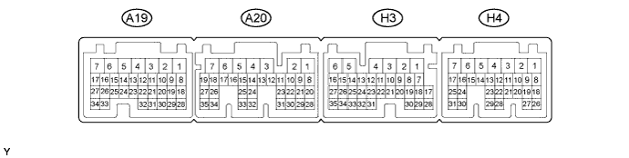
Disconnect the A20, H3 and H4 connectors.
-
Measure the voltage and resistance according to the value(s) in the table below.
Tester Connection Input/Output Wiring Color Terminal Description Condition Specified Condition Related Data List Item A20-2 (IG2D) - Body ground Output V - Body ground IG2 signal 20°C (68°F) 131 to 230 Ω IG2 Relay Monitor (Outside) A20-23 (STP) - Body ground Input L - Body ground Stop light switch signal Brake pedal depressed → Brake pedal released 9 V or higher → 1 V or less Stop Light Switch1 H3-1 (AM22) - Body ground Input W - Body ground +B power supply Always 9.5 to 14 V - H4-7 (AM21) - Body ground Input W - Body ground +B power supply Always 9.5 to 14 V - H3-6 (E1) - Body ground - W-B - Body ground Ground Always Below 1 Ω - H4-4 (E12) - Body ground - W-B - Body ground Ground Always Below 1 Ω - H4-24 (CA1L) - Body ground Input/Output V - Body ground CAN communication line Always 10 kΩ or higher - H4-25 (CA1H) - Body ground Input/Output P - Body ground CAN communication line Always 10 kΩ or higher - H4-17 (SSW2) - Body ground Input Y - Body ground SSW2 contact signal (backup for SSW1 and has same behavior as SSW1) Power switch pushed → power switch not pushed Below 1 Ω → 10 kΩ or higher Start Switch2 H3-7 (SSW1) - Body ground Input B - Body ground SSW1 contact signal Power switch pushed → power switch not pushed Below 1 Ω → 10 kΩ or higher Start Switch1 H4-1 (ACCD) - Body ground Output G - Body ground ACC signal 20°C (68°F) 81.49 to 118.98 Ω ACC Relay Monitor H4-2 (IG1D) - Body ground Output B - Body ground IG1 signal 20°C (68°F) 54.32 to 79.32 Ω IG1 Relay Monitor (Outside) H4-11 (LIN2) - Body ground Input/Output B - Body ground LIN communication line Always 10 kΩ or higher - If the result is not as specified, there may be a malfunction in the wire harness.
-
Reconnect the A20, H3 and H4 connectors.
-
Measure the voltage and check for pulses according to the value(s) in the table below.
Tester Connection Input/Output Wiring Color Terminal Description Condition Specified Condition Related Data List Item A20-2 (IG2D) - H3-6 (E1) Output V - W-B IG2 signal Power switch on (ACC) → power switch on (IG) 1 V or less → 9 V or higher IG2 Relay Monitor (Outside) H3-9 (INDW) - H3-6 (E1) Output G - W-B Power switch indicator (Amber) illumination output Brake pedal released, park (P) selected, power switch on (ACC), or on (IG) → Other than previous condition 7 V or higher → 1 V or less - A20-22 (PCON) - H3-6 (E1) Output LG - W-B P position signal Park (P) selected Pulse generation
(See waveform 1)
- A20-28 (PPOS) - H3-6 (E1) Input V - W-B P position signal Park (P) selected Pulse generation
(See waveform 1)
- H4-17 (SSW2) - H3-6 (E1) Output Y - W-B SSW2 contact signal (backup for SSW1 and has same behavior as SSW1) Power switch pushed → power switch not pushed 9 V or higher → 1 V or less Start Switch2 H3-7 (SSW1) - H3-6 (E1) Output B - W-B Power switch signal Power switch pushed → power switch not pushed 9 V or higher → 1 V or less Start Switch1 H4-1 (ACCD) - H3-6 (E1) Output G - W-B ACC signal Power switch off → power switch on (ACC) 1 V or less → 8.5 V or higher ACC Relay Monitor H4-2 (IG1D) - H3-6 (E1) Output B - W-B IG1 signal Power switch on (ACC) → power switch on (IG) 1 V or less → 9 V or higher IG1 Relay Monitor (Outside) H3-8 (INDS) - H3-6 (E1) Output R - W-B Power switch indicator (green) illumination output Brake pedal depressed, park (P) selected 7 V or higher - H3-14 (SPDI) - H3-6 (E1) Input V - W-B Vehicle speed signal Power switch on (IG), vehicle being driven at approx. 5 km/h (3 mph) Pulse generation
(See waveform 2)
Vehicle Speed Signal H4-20 (IMO) - H3-6 (E1) Output L - W-B ID code box (immobiliser code ECU) communication input
(Signal input from power management control ECU to ID code box (immobiliser code ECU))
Power switch off 11 to 14 V
-
Engine Start Request
-
EFI Code Receive
Within 3 seconds of hybrid control system start or within 3 seconds of power switch turned on (IG) after auxiliary battery cable disconnected and reconnected Pulse generation
(See waveform 3)
H4-21 (IMI) - H3-6 (E1) Input R - W-B ID code box (immobiliser code ECU) communication output
(Signal output from ID code box (immobiliser code ECU) to power management control ECU)
Power switch off 11 to 14 V Power switch on (IG) Pulse generation
(See waveform 3)
-
-
Using an oscilloscope, check the signal waveform of the ECU.
-
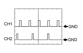
Waveform 1
Tester Connection CH1: A20-22 (PCON) - H3-6 (E1)
CH2: A20-28 (PPOS) - H3-6 (E1)
Tool Setting 10 V/DIV., 10 ms/DIV. Vehicle Condition Power switch on (IG) -
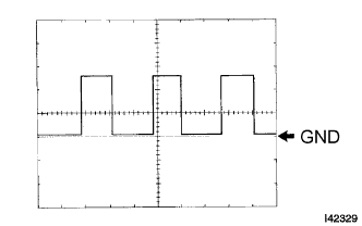
Waveform 2
Tester Connection H3-14 (SPDI) - H3-6 (E1) Tool Setting 5 V/DIV., 10 ms/DIV. Vehicle Condition Driving at approx. 20 km/h (12 mph) Tip:The wavelength becomes shorter as the vehicle speed increases.
-

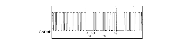
Waveform 1 (Reference)
Table 1. Text in Illustration *a Approximately 160 ms *b Approximately 510 ms Table 2. Measurement Condition Item Content Tester Connection H4-20 (IMO) - H3-6 (E1) Tool Setting 2 V/DIV., 200 ms/DIV. Condition Within 3 seconds of hybrid control system start or within 3 seconds of power switch turned on (IG) after auxiliary battery cable disconnected and reconnected -
Waveform 2 (Reference)
Table 3. Text in Illustration *a Approximately 160 ms *b Approximately 510 ms Table 4. Measurement Condition Item Content Tester Connection H4-21 (IMI) - H3-6 (E1) Tool Setting 2 V/DIV., 200 ms/DIV. Condition Power switch on (IG)
-
-
-
CHECK CERTIFICATION ECU (SMART KEY ECU ASSEMBLY)
-
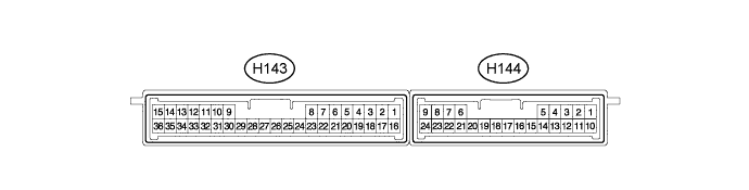
Disconnect the H143 certification ECU (smart key ECU assembly) connector.
-
Measure the voltage and resistance according to the value(s) in the table below.
Terminal No. (Symbol) Input/Output Wiring Color Terminal Description Condition Specified Condition Related Data List Item H143-15 (E) - Body ground - W-B - Body ground Ground Always Below 1 Ω - H143-1 (+B) - H143-15 (E) Input B - W-B +B power supply Always 11 to 14 V - H143-17 (CUTB) - H143-15 (E) Input Y - W-B Dark current cut pin* Always 11 to 14 V -
-
*: In order to prevent the auxiliary battery from being depleted when the vehicle is shipped long distances, a fuse that cuts unnecessary electrical load while the vehicle is being shipped is set in the circuit. If the fuse is removed, the circuit becomes open. If the fuse that is between the auxiliary battery and terminal CUTB is removed and the circuit is open, the certification ECU (smart key ECU assembly) changes to a certain control mode.
If the result is not as specified, there may be a malfunction on the wire harness side or the fuse is removed.
-
-
Reconnect the H143 certification ECU (smart key ECU assembly) connector.
-
Measure the voltage according to the value(s) in the table below.
Terminal No. (Symbol) Input/Output Wiring Color Terminal Description Condition Specified Condition Related Data List Item H143-16 (IG) - H143-15 (E) Input BE - W-B IG power supply Power switch off → on (IG) Below 1 V → 11 to 14 V Power Switch H143-7 (CLG5) - H143-15 (E) Output G - W-B Output to No. 1 indoor electrical key antenna assembly (front floor) Procedure:
-
Turn power switch off
-
Open door
-
Close door
-
Wait 30 seconds
Pulse generation (See waveform 1) Over Head + Front Room (key diagnostic mode) H143-8 (CG5B) - H143-15 (E) Output R - W-B Output to No. 1 indoor electrical key antenna assembly (front floor) (terminal on opposite side of component from CLG5 output terminal) Procedure:
-
Turn power switch off
-
Open door
-
Close door
-
Wait 30 seconds
Pulse generation (See waveform 1) Over Head + Front Room (key diagnostic mode) H143-24 (CLG6) - H143-15 (E) Output GR - W-B Output to No. 2 indoor electrical key antenna assembly (rear floor) Procedure:
-
Turn power switch off
-
Open door
-
Close door
-
Wait 30 seconds
Pulse generation (See waveform 1) Over Head + Rear Room (key diagnostic mode) H143-25 (CG6B) - H143-15 (E) Output BR - W-B Output to No. 2 indoor electrical key antenna assembly (rear floor) Proceed:
-
Turn power switch off
-
Open door
-
Close door
-
Wait 30 seconds
Pulse generation (See waveform 1) Over Head + Rear Room (key diagnostic mode) H143-26 (CLG7) - H143-15 (E) Output G - W-B Output to No. 3 indoor electrical key antenna assembly (luggage compartment) Proceed:
-
Turn power switch off
-
Open door
-
Close door
-
Wait 30 seconds
Pulse generation (See waveform 1) Over Head + Back Door (inside) (key diagnostic mode) H143-27 (CG7B) - H143-15 (E) Output R - W-B Output to No. 3 indoor electrical key antenna assembly (luggage compartment) Proceed:
-
Turn power switch off
-
Open door
-
Close door
-
Wait 30 seconds
Pulse generation (See waveform 1) Over Head + Back Door (inside) (key diagnostic mode) H144-5 (RCO) - H143-15 (E) Output R - W-B Output to door control receiver
(Power supply for door control receiver. Certification ECU (smart key ECU assembly) outputs 5 V when receiver starts operating.)
Procedure:
-
Turn power switch off
-
Take key outside vehicle but keep inside wireless function operational area*
-
Press lock or unlock button of key
Pulse generation (See waveform 2) - H144-15 (RDA) - H143-15 (E) Input Y - W-B Door control receiver verifies data received from key. Receiver sends data to ECU and intermittently grounds 12 V signal from certification ECU (smart key ECU assembly). Procedure:
-
Turn power switch off
-
Take key outside vehicle but keep inside wireless function operational area*
-
Lock all doors
-
Press lock or unlock button of key
Pulse generation (See waveform 3) - H144-16 (RSSI) - H143-15 (E) Input V - W-B Door control receiver sends signal to certification ECU (smart key ECU assembly) indicating whether electric waves (example: 312 MHz) from key are being received or not (receiver grounds 12 V signal from certification ECU (smart key ECU assembly)) Procedure:
-
Turn power switch off
-
Take key outside vehicle but keep inside wireless function operational area*
-
Lock all doors
-
Press lock or unlock button of key
Pulse generation (See waveform 4) -
-
*: For details about the areas that are inside the wireless function operational area, refer to Operation Check (Click here).
-
-
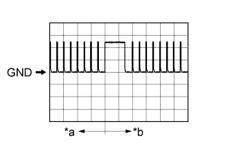
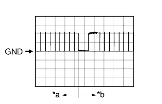
Using an oscilloscope, check waveform 1.
Tip:The oscilloscope waveform shown in the illustration is an example for reference only. Noise, chattering, etc. are not shown.
Table 5. Text in Illustration *a Door open *b After approximately 30 seconds from when the door is closed Table 6. Waveform 1 (Reference) Item Content Terminal No. (Symbol)
-
H143-7 (CLG5) - H143-15 (E)
-
H143-8 (CG5B) - H143-15 (E)
-
H143-24 (CLG6) - H143-15 (E)
-
H143-25 (CG6B) - H143-15 (E)
-
H143-26 (CLG7) - H143-15 (E)
-
H143-27 (CG7B) - H143-15 (E)
Tool Setting 2 V/DIV., 500 ms/DIV. Condition Procedure:
-
Turn power switch off
-
Open door
-
Close door
-
Wait 30 seconds
-
-
Using an oscilloscope, check waveform 2.
Tip:The oscilloscope waveform shown in the illustration is an example for reference only. Noise, chattering, etc. are not shown.
Table 7. Text in Illustration *a Before lock or unlock button of key pressed *b After lock or unlock button of key pressed Table 8. Waveform 2 (Reference) Item Content Terminal No. (Symbol) H144-5 (RCO) - H143-15 (E) Tool Setting 2 V/DIV., 500 ms/DIV. Condition Procedure:
-
Turn power switch off
-
Take key outside vehicle but keep inside wireless function operational area*
-
Press lock or unlock button of key
-
*: For details about the areas that are inside the wireless function operational area, refer to Operation Check (Click here).
-
-
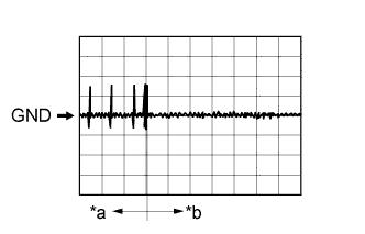
Using an oscilloscope, check waveform 3.
Tip:The oscilloscope waveform shown in the illustration is an example for reference only. Noise, chattering, etc. are not shown.
Table 9. Text in Illustration *a Before lock or unlock button of key pressed *b After lock or unlock button of key pressed Table 10. Waveform 3 (Reference) Item Content Terminal No. (Symbol) H144-15 (RDA) - H143-15 (E) Tool Setting 5 V/DIV., 500 ms/DIV. Condition Procedure:
-
Turn power switch off
-
Take key outside vehicle but keep inside wireless function operational area*
-
Lock all doors
-
Press lock or unlock button of key
-
*: For details about the areas that are inside the wireless function operational area, refer to Operation Check (Click here).
-
-
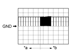
Using an oscilloscope, check waveform 4.
Tip:The oscilloscope waveform shown in the illustration is an example for reference only. Noise, chattering, etc. are not shown.
Table 11. Text in Illustration *a Before lock or unlock button of key pressed *b After lock or unlock button of key pressed Table 12. Waveform 4 (Reference) Item Content Terminal No. (Symbol) H144-16 (RSSI) - H143-15 (E) Tool Setting 5 V/DIV., 500 ms/DIV. Condition Procedure:
-
Turn power switch off
-
Take key outside vehicle but keep inside wireless function operational area*
-
Lock all doors
-
Press lock or unlock button of key
-
*: For details about the areas that are inside the wireless function operational area, refer to Operation Check (Click here).
-
-