ENTRY AND START SYSTEM (for Entry Function) Front Passenger Side Door Entry Lock and Unlock Functions do not Operate
DESCRIPTION
If the entry lock and unlock functions do not operate for the front passenger door only, the request code may not be being transmitted from the front passenger door or the front door outside handle assembly (for front passenger door) (touch sensor) may be malfunctioning. If the entry functions for other doors operate properly, communication between the key and door control receiver is normal. In this case, there may be a problem with request code transmission (communication between the certification ECU (smart key ECU assembly) and front door outside handle assembly (for front passenger door) [front passenger door electrical key antenna]), or there may be wave interference.
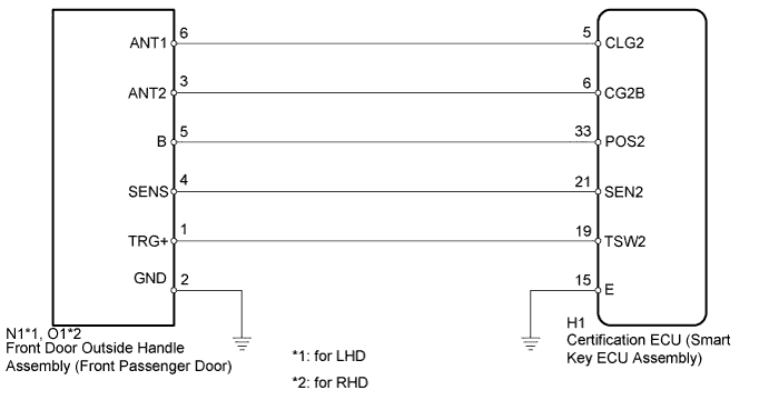
WIRING DIAGRAM
INSPECTION PROCEDURE
Note
-
The entry and start system (for Entry Function) uses a multiplex communication system (LIN communication system) and the CAN communication system. Inspect the communication function by following How to Proceed with Troubleshooting Click here. Troubleshoot the entry and start system (for Entry Function) after confirming that the communication systems are functioning properly.
-
When using the intelligent tester with the power switch off to troubleshoot:
Connect the intelligent tester to the DLC3 and turn a courtesy light switch on and off at 1.5-second intervals until communication between the intelligent tester and vehicle begins.
-
Check that there are no electrical key transmitters in the vehicle.
-
Before performing the inspection, check that DTC B1242 (wireless door lock control) is not output Click here.
-
Before replacing the certification ECU (smart key ECU assembly), refer to the entry and start system (for Entry Function) Click here.
PROCEDURE
-
CHECK POWER DOOR LOCK OPERATION
-
When the door control switch on the multiplex network master switch assembly is operated, check that the doors unlock and lock according to the switch operation Click here.
OK Door locks operate normally.
NG 
GO TO POWER DOOR LOCK CONTROL SYSTEM Click here
OK 
-
-
READ VALUE USING INTELLIGENT TESTER (DOOR LOCK POSITION SWITCH)
-
Connect the intelligent tester to the DLC3.
-
Turn the power switch on (IG).
-
Turn the intelligent tester on.
-
Enter the following menus: Body / Main Body / Data List.
-
Read the Data List according to the display on the intelligent tester.
Main Body Tester Display Measurement Item/Range Normal Condition Diagnostic Note FL Door Lock Pos*1 Front LH door lock position switch signal / UNLOCK or LOCK UNLOCK: Front LH door unlocked
LOCK: Front LH door locked
- FR Door Lock Pos*2 Front RH door lock position switch signal / UNLOCK or LOCK UNLOCK: Front RH door unlocked
LOCK: Front RH door locked
-
-
*1: for RHD
-
*2: for LHD
OK On the intelligent tester screen, the display changes between LOCK and UNLOCK as shown in the chart above. -
NG
GO TO LIGHTING SYSTEM (Proceed to Door Unlock Detection Switch Circuit) Click here
OK
-
-
CHECK ELECTRICAL KEY ANTENNAS IN KEY DIAGNOSTIC MODE
-
Check the following antennas in the key diagnostic mode Click here.
-
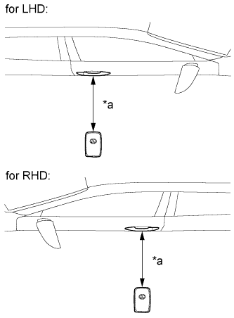
Text in Illustration *a 0.7 to 1 m (2.30 to 3.28 ft.) Check the electrical key antenna (for front passenger door):
When the electrical key transmitter is brought within 0.7 to 1 m (2.30 to 3.28 ft.) of the front door outside handle assembly (for front passenger door), check that the wireless door lock buzzer sounds.
OK Entry function operates normally.
-
NG 
CHECK HARNESS AND CONNECTOR (FRONT DOOR OUTSIDE HANDLE - CERTIFICATION ECU) Click here
OK 
REPLACE CERTIFICATION ECU (SMART KEY ECU ASSEMBLY)
-
-
CHECK HARNESS AND CONNECTOR (FRONT DOOR OUTSIDE HANDLE - CERTIFICATION ECU)
-
Disconnect the N1*1, O1*2 front door outside handle assembly (for front passenger door) connector.
-
Disconnect the H1 certification ECU (smart key ECU assembly) connector.
-
Measure the resistance according to the value(s) in the table below.
-
*1: for LHD
-
*2: for RHD
Standard Resistance for LHD Tester Connection Condition Specified Condition N1-3 (ANT2) - H1-6 (CG2B) Always Below 1 Ω N1-6 (ANT1) - H1-5 (CLG2) Always Below 1 Ω N1-5 (B) - H1-33 (POS2) Always Below 1 Ω N1-2 (GND) - Body ground Always Below 1 Ω N1-3 (ANT2) or H1-6 (CG2B) - Body ground Always 10 kΩ or higher N1-6 (ANT1) or H1-5 (CLG2) - Body ground Always 10 kΩ or higher N1-5 (B) or H1-33 (POS2) - Body ground Always 10 kΩ or higher for RHD Tester Connection Condition Specified Condition O1-3 (ANT2) - H1-6 (CG2B) Always Below 1 Ω O1-6 (ANT1) - H1-5 (CLG2) Always Below 1 Ω O1-5 (B) - H1-33 (POS2) Always Below 1 Ω O1-2 (GND) - Body ground Always Below 1 Ω O1-3 (ANT2) or H1-6 (CG2B) - Body ground Always 10 kΩ or higher O1-6 (ANT1) or H1-5 (CLG2) - Body ground Always 10 kΩ or higher O1-5 (B) or H1-33 (POS2) - Body ground Always 10 kΩ or higher -
NG
REPAIR OR REPLACE HARNESS OR CONNECTOR
OK
-
-
CHECK CERTIFICATION ECU (SMART KEY ECU ASSEMBLY) (OUTPUT TO FRONT PASSENGER DOOR ELECTRICAL KEY ANTENNA)
-
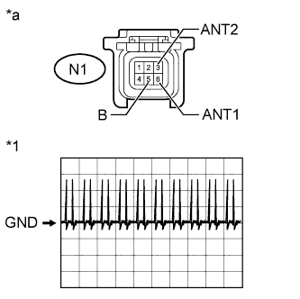
Text in Illustration *1 Waveform *a Front view of wire harness connector
(to Front Door Outside Handle Assembly (for Front Passenger Door))
Disconnect the N1*1, O1*2 front door outside handle assembly (for front passenger door) connector.
-
Connect the H1 certification ECU (smart key ECU assembly) connector.
-
Measure the voltage according to the value(s) in the table below.
-
*1: for LHD
-
*2: for RHD
Standard Voltage for LHD Tester Connection Condition Specified Condition N1-5 (B) - Body ground Power switch off → on (IG) 9 to 14 V → Below 2 V for RHD Tester Connection Condition Specified Condition O1-5 (B) - Body ground Power switch off → on (IG) 9 to 14 V → Below 2 V -
-
Using an oscilloscope, check the waveform.
OK Tester Connection Switch Condition Tool Setting Specified Condition N1-3 (ANT2) - N1-6 (ANT1) Procedure:
-
Power switch off
-
Key brought outside vehicle
-
All doors closed
-
Key not inside vehicle
-
All doors locked through wireless operation
2 V/DIV., 500 ms/DIV. Pulse generation (See waveform) -
NG
REPLACE CERTIFICATION ECU (SMART KEY ECU ASSEMBLY)
OK
-
-
REPLACE FRONT DOOR OUTSIDE HANDLE ASSEMBLY (FOR FRONT PASSENGER DOOR)
-
Temporarily replace the front door outside handle assembly (for front passenger door) with a new or normally functioning one Click here.
NEXT
-
-
CHECK FRONT DOOR OUTSIDE HANDLE ASSEMBLY (OPERATION)
-
Check that the entry functions operate normally Click here.
OK Entry functions operate normally.
NG
REPLACE CERTIFICATION ECU (SMART KEY ECU ASSEMBLY)
OK
END (FRONT DOOR OUTSIDE HANDLE ASSEMBLY WAS DEFECTIVE)
-