WIRELESS DOOR LOCK CONTROL SYSTEM TERMINALS OF ECU
-
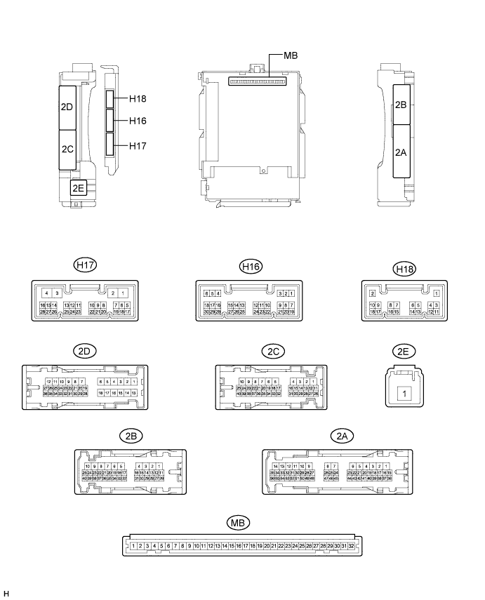
CHECK INSTRUMENT PANEL JUNCTION BLOCK ASSEMBLY AND MAIN BODY ECU (MULTIPLEX NETWORK BODY ECU)
-
Disconnect the MB and H17 main body ECU (multiplex network body ECU) connector.
-
Disconnect the 2B and 2C instrument panel junction block assembly connector.
-
Measure the voltage and resistance according to the value(s) in the table below.
Tech Tips
Measure the values on the wire harness side with the connectors disconnected.
Tester Connection Wiring Color Terminal Description Condition Specified Condition 2B-6 (GND1) - Body ground W-B - Body ground Ground Always Below 1 Ω 2C-18 (BECU) - Body ground B - Body ground Auxiliary battery power supply Power switch off 11 to 14 V H17-3 (GND2) - Body ground W-B - Body ground Ground Always Below 1 Ω MB-29 (ACC) - Body ground - ACC power supply Power switch on (ACC) 11 to 14 V MB-29 (ACC) - Body ground - ACC power supply Power switch off Below 1 V MB-31 (ALTB) - Body ground - Auxiliary battery power supply Power switch off 11 to 14 V MB-32 (IG) - Body ground - Power switch power supply Power switch on (IG) 11 to 14 V MB-32 (IG) - Body ground - Power switch power supply Power switch off Below 1 V If the result is not as specified, there may be a malfunction in the wire harness.
-
Reconnect the MB and H17 main body ECU (multiplex network body ECU) connector.
-
Reconnect the 2B and 2C instrument panel junction block assembly connector.
-
Measure the voltage and check for pulses according to the value(s) in the table below.
Tester Connection Wiring Color Terminal Description Condition Specified Condition 2B-1 (ACT-) - Body ground B - Body ground Door lock motor unlock drive output (except driver side) Multiplex network master switch (door control switch) or driver door key cylinder off Below 1 V 2B-1 (ACT-) - Body ground B - Body ground Door lock motor unlock drive output (except driver side) Multiplex network master switch (door control switch) or driver door key cylinder unlocked 11 to 14 V 2B-8 (ACT+) - Body ground L - Body ground Door lock motor lock drive output (all doors) Multiplex network master switch (door control switch) or driver door key cylinder off Below 1 V 2B-8 (ACT+) - Body ground L - Body ground Door lock motor lock drive output (all doors) Multiplex network master switch (door control switch) or driver door key cylinder locked 11 to 14 V 2B-5 (ACTD) - Body ground B - Body ground Driver door lock motor unlock drive output Multiplex network master switch (door control switch) or driver door key cylinder off Below 1 V 2B-5 (ACTD) - Body ground B - Body ground Driver door lock motor unlock drive output Multiplex network master switch (door control switch) or driver door key cylinder unlocked 11 to 14 V 2D-35 (FLCY) - Body ground BR - Body ground Driver door courtesy switch input*1
Front passenger door courtesy switch input*2
Driver door open*1
Front passenger door open*2
Below 1 V 2D-35 (FLCY) - Body ground BR - Body ground Driver door courtesy switch input*1
Front passenger door courtesy switch input*2
Driver door closed*1
Front passenger door closed*2
11 to 14 V 2D-36 (FRCY) - Body ground BR - Body ground Front passenger door courtesy switch input*1
Driver door courtesy switch input*2
Front passenger door open*1
Driver door open*2
Below 1 V 2D-36 (FRCY) - Body ground BR - Body ground Front passenger door courtesy switch input*1
Driver door courtesy switch input*2
Front passenger door closed*1
Driver door closed*2
11 to 14 V H18-3 (LCTY) - Body ground G - Body ground Rear door LH courtesy light switch input Rear door LH open Below 1 V H18-3 (LCTY) - Body ground G - Body ground Rear door LH courtesy light switch input Rear door LH closed Pulse generation H16-6 (RCTY) - Body ground G - Body ground Rear door RH courtesy light switch input Rear door RH open Below 1 V H16-6 (RCTY) - Body ground G - Body ground Rear door RH courtesy light switch input Rear door RH closed Pulse generation H16-7 (LSFL) - Body ground GR - Body ground Driver door unlock detection switch input*1
Front passenger door unlock detection switch input*2
Driver door unlocked*1
Front passenger door unlocked*2
Below 1 V H16-7 (LSFL) - Body ground GR - Body ground Driver door unlock detection switch input*1
Front passenger door unlock detection switch input*2
Power switch off, all doors closed and driver door locked*1
Power switch off, all doors closed and front passenger door locked*2
Pulse generation H16-18 (LSFR) - Body ground SB - Body ground Front passenger door unlock detection switch input*1
Driver door unlock detection switch input*2
Front passenger door unlocked*1
Driver door unlocked*2
Below 1 V H16-18 (LSFR) - Body ground SB - Body ground Front passenger door unlock detection switch input*1
Driver door unlock detection switch input*2
Power switch off, all doors closed and front passenger door locked*1
Power switch off, all doors closed and driver door locked*2
Pulse generation H17-2 (LSWR) - Body ground GR - Body ground Rear door RH unlock detection switch input Rear right door unlocked Below 1 V H17-2 (LSWR) - Body ground GR - Body ground Rear door RH unlock detection switch input Power switch off, all doors closed and rear right door locked 11 to 14 V 2D-25 (LSWL) - Body ground GR - Body ground Rear door LH unlock detection switch input Rear door LH unlocked Below 1 V 2D-25 (LSWL) - Body ground GR - Body ground Rear door LH unlock detection switch input Power switch off, all doors closed and rear door LH locked 11 to 14 V 2C-23 (BZR) - Body ground R - Body ground Wireless door lock buzzer signal Wireless door lock buzzer off Below 1 V 2C-23 (BZR) - Body ground R - Body ground Wireless door lock buzzer signal Wireless door lock buzzer on Pulse generation H16-3 (HAZ) - Body ground Y - Body ground Turn signal flasher relay signal Electrical key transmitter switch not pressed 11 to 14 V H16-3 (HAZ) - Body ground Y - Body ground Turn signal flasher relay signal Any electrical key transmitter switch pressed Below 1 V *1: for LHD
*2: for RHD
If the result is not as specified, the main body ECU (multiplex network body ECU) or instrument panel junction block assembly may have a malfunction.
-
-
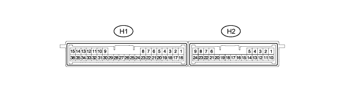
CHECK CERTIFICATION ECU (SMART KEY ECU ASSEMBLY) (w/ Entry Function)
-
Disconnect the H1 and H2 certification ECU (smart key ECU assembly) connectors.
-
Measure the resistance and voltage according to the value(s) in the table below.
Terminal No. (Symbol) Wiring Color Terminal Description Condition Specified Condition H1-15 (E) - Body ground W-B - Body ground Ground Always Below 1 Ω H1-1 (+B) - H1-15 (E) B - W-B Auxiliary battery power supply Power switch off 11 to 14 V H1-17 (CUTB) - H1-15 (E) Y - W-B Dark current cut pin Power switch off 11 to 14 V
-
If the result is not as specified, there may be a malfunction in the wire harness.
-
-
Reconnect the H1 and H2 certification ECU (smart key ECU assembly) connectors.
-
Measure the voltage according to the value(s) in the table below.
Terminal No. (Symbol) Wiring Color Terminal Description Condition Specified Condition H1-16 (IG) - H1-15 (E) BE - W-B IG power supply Power switch on (IG) 11 to 14 V Power switch off Below 1 V H2-16 (RSSI) - H1-15 (E) V - W-B Door control receiver output signal Power switch off, all doors closed and electrical key transmitter switch not pressed 11 to 14 V Power switch off, all doors closed and electrical key transmitter switch pressed Below 2 V H2-15 (RDA) - H1-15 (E) Y - W-B Door control receiver data input signal Power switch off, all doors closed and transmitter switch not pressed 11 to 14 V pulse generation at regular intervals Power switch off, all doors closed and transmitter switch pressed Pulse generation H2-5 (RC0) - H1-15 (E) R - W-B Supply battery to door control receiver Power switch off, all doors closed and electrical key transmitter switch pressed 4.5 to 5.5 V
-
If the result is not as specified, the certification ECU (smart key ECU assembly) may have a malfunction.
-
-
-
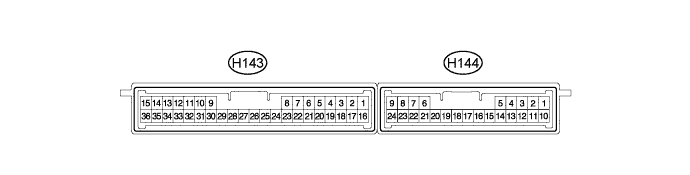
CHECK CERTIFICATION ECU (SMART KEY ECU ASSEMBLY) (w/o Entry Function)
-
Disconnect the H143 and H144 certification ECU (smart key ECU assembly) connectors.
-
Measure the resistance and voltage according to the value(s) in the table below.
Terminal No. (Symbol) Wiring Color Terminal Description Condition Specified Condition H143-15 (E) - Body ground W-B - Body ground Ground Always Below 1 Ω H143-1 (+B) - H143-15 (E) B - W-B Auxiliary battery power supply Power switch off 11 to 14 V H143-17 (CUTB) - H143-15 (E) Y - W-B Dark current cut pin Power switch off 11 to 14 V
-
If the result is not as specified, there may be a malfunction in the wire harness.
-
-
Reconnect the H143 and H144 certification ECU (smart key ECU assembly) connectors.
-
Measure the voltage according to the value(s) in the table below.
Terminal No. (Symbol) Wiring Color Terminal Description Condition Specified Condition H143-16 (IG) - H143-15 (E) BE - W-B IG power supply Power switch on (IG) 11 to 14 V Power switch off Below 1 V H144-16 (RSSI) - H143-15 (E) V - W-B Door control receiver output signal Power switch off, all doors closed and electrical key transmitter switch not pressed 11 to 14 V Power switch off, all doors closed and electrical key transmitter switch pressed Below 2 V H144-15 (RDA) - H143-15 (E) Y - W-B Door control receiver data input signal Power switch off, all doors closed and transmitter switch not pressed 11 to 14 V pulse generation at regular intervals Power switch off, all doors closed and transmitter switch pressed Pulse generation H144-5 (RC0) - H143-15 (E) R - W-B Supply battery to door control receiver Power switch off, all doors closed and electrical key transmitter switch pressed 4.5 to 5.5 V
-
If the result is not as specified, the certification ECU (smart key ECU assembly) may have a malfunction.
-
-