CAN COMMUNICATION SYSTEM Check CAN Bus Line for Short to +B (LHD Models)
DESCRIPTION
There may be a short circuit between one of the CAN bus lines and +B when no resistance exists between terminals 6 (CANH) and 16 (BAT) or 14 (CANL) and 16 (BAT) of the DLC3.
| Symptom | Trouble Area |
|---|---|
| No resistance exists between terminals 6 (CANH) and 16 (BAT) or 14 (CANL) and 16 (BAT) of DLC3. |
|
*1: w/ Navigation system (for DVD)
*2: w/ Navigation system (for HDD)
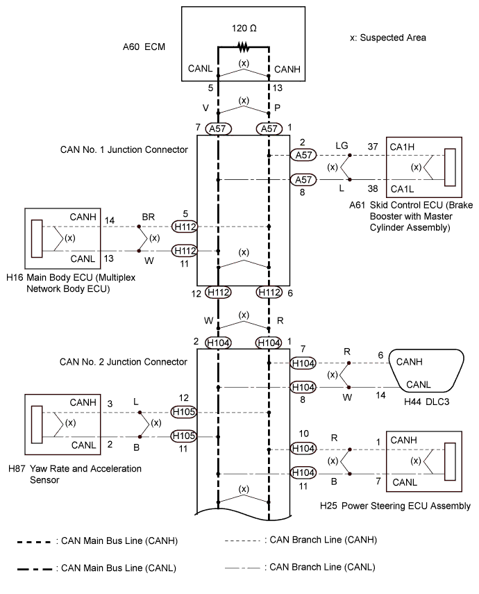
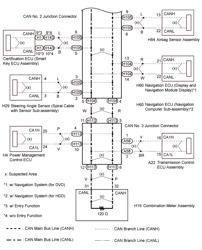
WIRING DIAGRAM
INSPECTION PROCEDURE
Note
-
After turning the power switch off, waiting time may be required before disconnecting the cable from the negative (-) auxiliary battery terminal. Therefore, make sure to read the disconnecting the cable from the negative (-) auxiliary battery terminal notices before proceeding with work Click here.
-
Turn the power switch off before measuring the resistances between CAN main bus lines and between CAN branch lines.
-
Turn the power switch off before inspecting CAN bus lines for a ground short.
-
After the power switch is turned off, check that the key reminder warning system and light reminder warning system are not operating.
-
Before measuring the resistance, leave the vehicle as is for at least 1 minute and do not operate the power switch, any other switches or the doors. If any doors need to be opened in order to check connectors, open the doors and leave them open.
Tech Tips
-
Operating the power switch, any other switches or a door triggers related ECU and sensor communication on the CAN. This communication will cause the resistance value to change.
-
Even after DTCs are cleared, if a DTC is stored again after driving the vehicle for a while, the malfunction may be occurring due to vibration of the vehicle. In such a case, wiggling the ECUs or wire harness while performing the inspection below may help determine the cause of the malfunction.
PROCEDURE
-
CHECK FOR SHORT TO +B IN CAN BUS LINE (CAN NO. 2 J/C)
-
Disconnect the cable from the negative (-) auxiliary battery terminal.
-
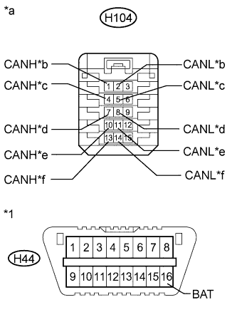
Text in Illustration *1 DLC3 *a Front view of wire harness connector
(to CAN No. 2 Junction Connector)
*b to CAN No. 1 Junction Connector *c to CAN No. 3 Junction Connector *d to DLC3 *e to Power Steering ECU Assembly *f to Navigation ECU Disconnect the wire harness connector from the CAN No. 2 junction connector rear side.
-
Measure the resistance according to the value(s) in the table below.
Standard Resistance Tester Connection Condition Specified Condition Connected to H104-1 (CANH) - H44-16 (BAT) Cable disconnected from negative (-) auxiliary battery terminal 6 kΩ or higher CAN No. 1 junction connector H104-2 (CANL) - H44-16 (BAT) H104-4 (CANH) - H44-16 (BAT) Cable disconnected from negative (-) auxiliary battery terminal 6 kΩ or higher CAN No. 3 junction connector H104-5 (CANL) - H44-16 (BAT) H104-7 (CANH) - H44-16 (BAT) Cable disconnected from negative (-) auxiliary battery terminal 6 kΩ or higher DLC3 H104-8 (CANL) - H44-16 (BAT) H104-10 (CANH) - H44-16 (BAT) Cable disconnected from negative (-) auxiliary battery terminal 6 kΩ or higher Power steering ECU assembly H104-11 (CANL) - H44-16 (BAT) H104-13 (CANH) - H44-16 (BAT) Cable disconnected from negative (-) auxiliary battery terminal 6 kΩ or higher Navigation ECU H104-14 (CANL) - H44-16 (BAT) Result Result Proceed to OK A NG (DLC3 branch line) B NG (CAN No. 1 junction connector main line) C NG (CAN No. 3 junction connector main line) D NG (ECU or sensor wire) E
B 
REPAIR OR REPLACE CAN BRANCH LINE CONNECTED TO DLC3
C 
CHECK FOR SHORT TO +B IN CAN BUS LINE (CAN NO. 1 J/C) Click here
D
CHECK FOR SHORT TO +B IN CAN BUS LINE (CAN NO. 3 J/C) Click here
E
CHECK FOR SHORT TO +B IN CONNECTED COMPONENT (ECU, SENSOR) Click here
A 
-
-
CHECK FOR SHORT TO +B IN CAN BUS LINE (CAN NO. 2 J/C)
-
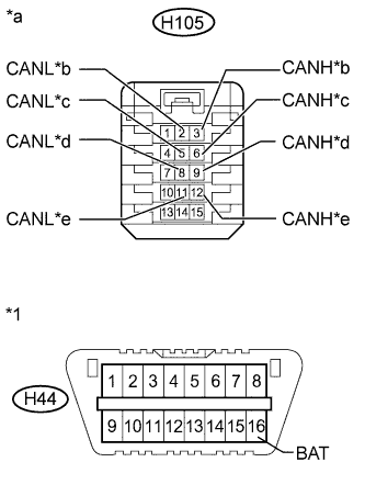
Text in Illustration *1 DLC3 *a Front view of wire harness connector
(to CAN No. 2 Junction Connector)
*b to Steering Angle Sensor (Spiral Cable with Sensor Sub-assembly) *c to Certification ECU (Smart Key ECU Assembly) *d to Airbag Sensor Assembly *e to Yaw Rate and Acceleration Sensor Disconnect the wire harness connector from the CAN No. 2 junction connector front side.
-
Measure the resistance according to the value(s) in the table below.
Standard Resistance Tester Connection Condition Specified Condition Connected to H105-3 (CANH) - H44-16 (BAT) Cable disconnected from negative (-) auxiliary battery terminal 6 kΩ or higher Steering angle sensor (Spiral cable with sensor sub-assembly) H105-2 (CANL) - H44-16 (BAT) H105-6 (CANH) - H44-16 (BAT) Cable disconnected from negative (-) auxiliary battery terminal 6 kΩ or higher Certification ECU (Smart key ECU assembly) H105-5 (CANL) - H44-16 (BAT) H105-9 (CANH) - H44-16 (BAT) Cable disconnected from negative (-) auxiliary battery terminal 6 kΩ or higher Airbag sensor assembly H105-8 (CANL) - H44-16 (BAT) H105-12 (CANH) - H44-16 (BAT) Cable disconnected from negative (-) auxiliary battery terminal 6 kΩ or higher Yaw rate and acceleration sensor H105-11 (CANL) - H44-16 (BAT) Result Result Proceed to OK A NG (ECU or sensor wire) B
B
CHECK FOR SHORT TO +B IN CONNECTED COMPONENT (ECU, SENSOR) Click here
A 
REPLACE CAN NO. 2 JUNCTION CONNECTOR
-
-
CHECK FOR SHORT TO +B IN CAN BUS LINE (CAN NO. 1 J/C)
-
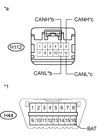
Text in Illustration *1 DLC3 *a Front view of wire harness connector
(to CAN No. 1 Junction Connector)
*b to Main Body ECU (Multiplex Network Body ECU) *c to CAN No. 2 Junction Connector Disconnect the instrument panel wire from the CAN No. 1 junction connector.
-
Measure the resistance according to the value(s) in the table below.
Standard Resistance Tester Connection Condition Specified Condition Connected to H112-5 (CANH) - H44-16 (BAT) Cable disconnected from negative (-) auxiliary battery terminal 6 kΩ or higher Main body ECU (Multiplex network body ECU) H112-11 (CANL) - H44-16 (BAT) H112-6 (CANH) - H44-16 (BAT) Cable disconnected from negative (-) auxiliary battery terminal 6 kΩ or higher CAN No. 2 junction connector H112-12 (CANL) - H44-16 (BAT) Result Result Proceed to OK A NG (CAN No. 2 junction connector main line) B NG (Main body ECU branch line) C
B
REPAIR OR REPLACE CAN MAIN BUS LINE OR CONNECTOR (CAN NO. 1 J/C - CAN NO. 2 J/C)
C
CHECK FOR SHORT TO +B IN CONNECTED COMPONENT (ECU, SENSOR) Click here
A
-
-
CHECK FOR SHORT TO +B IN CAN BUS LINE (CAN NO. 1 J/C)
-
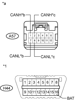
Text in Illustration *1 DLC3 *a Front view of wire harness connector
(to CAN No. 1 Junction Connector)
*b to ECM *c to Skid Control ECU Disconnect the engine room main wire from the CAN No. 1 junction connector.
-
Measure the resistance according to the value(s) in the table below.
Standard Resistance Tester Connection Condition Specified Condition Connected to A57-1 (CANH) - H44-16 (BAT) Cable disconnected from negative (-) auxiliary battery terminal 6 kΩ or higher ECM A57-7 (CANL) - H44-16 (BAT) A57-2 (CANH) - H44-16 (BAT) Cable disconnected from negative (-) auxiliary battery terminal 6 kΩ or higher Skid Control ECU (Brake Booster with Master Cylinder Assembly) A57-8 (CANL) - H44-16 (BAT) Result Result Proceed to OK A NG (ECU or sensor wire) B
B
CHECK FOR SHORT TO +B IN CONNECTED COMPONENT (ECU, SENSOR) Click here
A
REPLACE CAN NO. 1 JUNCTION CONNECTOR
-
-
CHECK FOR SHORT TO +B IN CAN BUS LINE (CAN NO. 3 J/C)
-
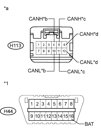
Text in Illustration *1 DLC3 *a Front view of wire harness connector
(to CAN No. 3 Junction Connector)
*b to Power Management Control ECU *c to CAN No. 2 Junction Connector *d to Combination Meter Assembly Disconnect the instrument panel wire from the CAN No. 3 junction connector.
-
Measure the resistance according to the value(s) in the table below.
Standard Resistance Tester Connection Condition Specified Condition Connected to H113-4 (CANH) - H44-16 (BAT) Cable disconnected from negative (-) auxiliary battery terminal 6 kΩ or higher Power management control ECU H113-10 (CANL) - H44-16 (BAT) H113-5 (CANH) - H44-16 (BAT) Cable disconnected from negative (-) auxiliary battery terminal 6 kΩ or higher CAN No. 2 junction connector H113-11 (CANL) - H44-16 (BAT) H113-6 (CANH) - H44-16 (BAT) Cable disconnected from negative (-) auxiliary battery terminal 6 kΩ or higher Combination meter assembly H113-12 (CANL) - H44-16 (BAT) Result Result Proceed to OK A NG (CAN No. 2 junction connector main line) B NG (ECU or sensor wire) C
B
REPAIR OR REPLACE CAN MAIN BUS LINE OR CONNECTOR (CAN NO. 2 J/C - CAN NO. 3 J/C)
C
CHECK FOR SHORT TO +B IN CONNECTED COMPONENT (ECU, SENSOR) Click here
A
-
-
CHECK FOR SHORT TO +B IN CAN BUS LINE (CAN NO. 3 J/C)
-
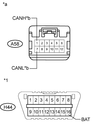
Text in Illustration *1 DLC3 *a Front view of wire harness connector
(to CAN No. 3 Junction Connector)
*b to Transmission Control ECU Assembly Disconnect the engine room main wire from the CAN No. 3 junction connector.
-
Measure the resistance according to the value(s) in the table below.
Standard Resistance Tester Connection Condition Specified Condition Connected to A58-1 (CANH) - H44-16 (BAT) Cable disconnected from negative (-) auxiliary battery terminal 6 kΩ or higher Transmission control ECU A58-7 (CANL) - H44-16 (BAT) Result Result Proceed to OK A NG (Transmission control ECU assembly branch line) B
B
CHECK FOR SHORT TO +B IN CONNECTED COMPONENT (ECU, SENSOR) Click here
A
REPLACE CAN NO. 3 JUNCTION CONNECTOR
-
-
CHECK FOR SHORT TO +B IN CONNECTED COMPONENT (ECU, SENSOR)
-
Reconnect all wire harness connectors (CAN J/C1, CAN J/C2 and CAN J/C3).
-
Disconnect the ECU or sensor connected to the CAN bus line that is shorted to +B.
Tech Tips
If the ECU or sensor has multiple connectors, disconnect the connector that includes the CAN bus lines. To determine the ECU or sensor that is connected to the shorted bus line, refer to the terminals of ECU tables Click here.
-
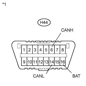
Text in Illustration *1 DLC3 Measure the resistance according to the value(s) in the table below.
Standard Resistance Tester Connection Condition Specified Condition H44-6 (CANH) - H44-16 (BAT) Cable disconnected from negative (-) auxiliary battery terminal 6 kΩ or higher H44-14 (CANL) - H44-16 (BAT) Tech Tips
If the resistance changes to 6 kΩ or higher when the connector is disconnected from the ECU (or sensor), there may be a short in the ECU (or sensor).
NG
REPAIR OR REPLACE CORRESPONDING ECU/SENSOR WIRE OR CONNECTOR
OK
REPLACE CORRESPONDING ECU OR SENSOR
-