CAN COMMUNICATION SYSTEM PRECAUTION
-
NOTICE FOR INITIALIZATION
Note
When disconnecting the cable from the negative (-) auxiliary battery terminal, initialize the following systems after the cable is reconnected.
System Name See Procedure Parking Assist Monitor System Power Door Lock Control System -
PRECAUTIONS FOR STEERING SYSTEM HANDLING
-
Be careful when replacing parts. Incorrect replacement could affect the performance of the steering system and result in hazardous driving.
-
-
PRECAUTIONS FOR SRS AIRBAG SYSTEM HANDLING
-
This vehicle is equipped with a Supplemental Restraint System (SRS) which includes parts such as airbags for the driver and front passenger. Failure to carry out service operations in the correct sequence could cause unexpected SRS deployment during servicing and may cause a serious accident. Before servicing (including removal or installation of parts, inspection or replacement), be sure to read Precaution for SRS Click here.
-
-
BUS LINE REPAIR
-
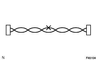
After repairing a bus line with solder, wrap the repaired part with electrical tape.
Note
-
The CANL bus line and CANH bus line must be installed together at all times.
-
When installing, make sure that these lines are twisted, because CAN bus lines are likely to be influenced by electrical noise if the bus lines are not twisted.
-
The difference in length between the CANL bus line and CANH bus line should be 100 mm (3.937 in.) or less.
-
Leave approximately 80 mm (3.150 in.) loose in the twisted wires around the connector.
-
-
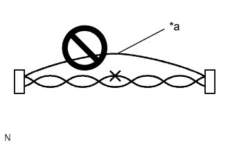
Text in Illustration *a Bypass Wire Do not use bypass wiring between connectors.
Note
The ability of the twisted bus lines to resist interference will be lost if bypass wiring is used.
-
-
CONNECTOR HANDLING
-
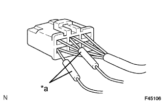
Text in Illustration *a Tester Probe When checking resistance with a tester, insert the tester probes from the backside (harness side) of the connector.
-
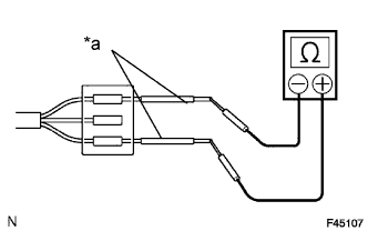
Text in Illustration *a Service Wire Use service wires to check the connector if it is impossible to check continuity from the rear of the connector.
-
-
PRECAUTIONS FOR INSPECTING OR REPLACING CAN JUNCTION CONNECTOR
-
If the CAN junction connector is removed from the vehicle for inspection or replacement, make sure to install the CAN junction connector and all wire harnesses to their original locations with tape and the clamps.
-