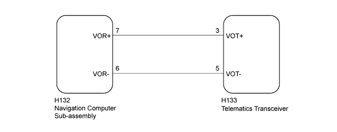
G-BOOK SYSTEM Received Voice Signal Circuit
WIRING DIAGRAM
INSPECTION PROCEDURE
Tech Tips
When replacing the navigation computer sub-assembly or telematics transceiver, perform the vehicle contract setting Click here.
PROCEDURE
-
CHECK HARNESS AND CONNECTOR (NAVIGATION COMPUTER SUB-ASSEMBLY - TELEMATICS TRANSCEIVER)
-
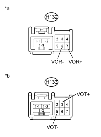
Text in Illustration *a Front view of wire harness connector
(to Navigation Computer Sub-assembly)
*b Front view of wire harness connector
(to Telematics Transceiver)
Disconnect the H132 navigation computer sub-assembly connector.
-
Disconnect the H133 telelmatics transceiver connector.
-
Measure the resistance according to the value(s) in the table below.
Standard Resistance Tester Connection Condition Specified Condition H132-7 (VOR+) - H133-3 (VOT+) Always Below 1 Ω H132-6 (VOR-) - H133-5 (VOT-) Always Below 1 Ω H132-7 (VOR+) - Body ground Always 10 kΩ or higher H132-6 (VOR-) - Body ground Always 10 kΩ or higher
NG 
REPAIR OR REPLACE HARNESS OR CONNECTOR
OK 
-
-
INSPECT TELEMATICS TRANSCEIVER
-
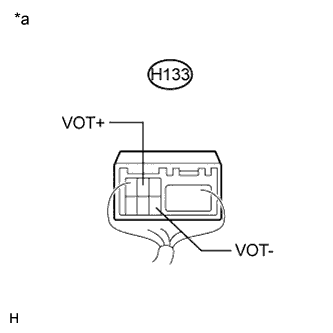
Text in Illustration *a Component with harness connected
(Telelmatics Transceiver)
Check for pulses according to the value(s) in the table below.
Standard Tester Connection Condition Specified Condition H133-3 (VOT+) - Body ground Receiving a call while using the operator service A waveform synchronized with the received voice is output. H133-5 (VOT-) - Body ground Receiving a call while using the operator service A waveform synchronized with the received voice is output.
NG
REPLACE TELEMATICS TRANSCEIVER Click here
OK 
REPLACE NAVIGATION COMPUTER SUB-ASSEMBLY Click here
-