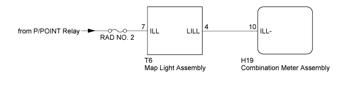
G-BOOK SYSTEM Emergency Call Switch Illumination Circuit
WIRING DIAGRAM
INSPECTION PROCEDURE
Note
Inspect the fuses for circuits related to this system before performing the following inspection procedure.
PROCEDURE
-
CHECK HARNESS AND CONNECTOR (MAP LIGHT ASSEMBLY - BODY GROUND)
-
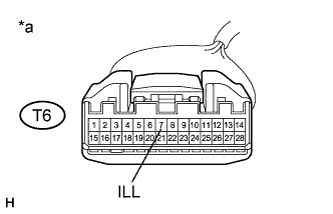
Text in Illustration *a Front view of wire harness connector
(to Map Light Assembly)
Disconnect the T6 map light assembly connector.
-
Measure the voltage according to the value(s) in the table below.
Standard Voltage Tester Connection Condition Specified Condition T6-7 (ILL) - Body ground Power switch on (IG) 11 to 14 V
NG 
REPAIR OR REPLACE HARNESS OR CONNECTOR
OK 
-
-
CHECK HARNESS AND CONNECTOR (MAP LIGHT ASSEMBLY - COMBINATION METER ASSEMBLY)
-
Disconnect the T6 map light assembly connector.
-
Disconnect the H19 combination meter assembly connector.
-
Measure the resistance according to the value(s) in the table below.
Standard Resistance Tester Connection Condition Specified Condition T6-4 (LILL) - H19-10 (ILL-) Always Below 1 Ω T6-4 (LILL) - Body ground Always 10 kΩ or higher
NG
REPAIR OR REPLACE HARNESS OR CONNECTOR
OK
-
-
INSPECT MAP LIGHT ASSEMBLY
-
Disconnect the T6 map light assembly connector.
-
Connect 4 1.5 V dry-cell batteries in series.
-
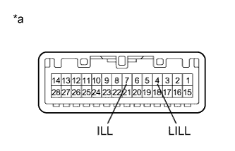
Text in Illustration *a Component without harness connected
(Map Light Assembly)
Connect the positive lead from the batteries to terminal 7 (ILL), and the negative lead to terminal 4 (LILL) of the map light assembly connector.
-
Check if the illumination for the emergency call switch comes on.
OK Illumination for the emergency call switch comes on.
NG
REPLACE MAP LIGHT ASSEMBLY Click here
OK 
REPLACE COMBINATION METER ASSEMBLY Click here
-