- Click here
PRECAUTION
Note:After turning the power switch off, waiting time may be required before disconnecting the cable from the negative (-) battery terminal. Therefore, make sure to read the disconnecting the cable from the negative (- ) battery terminal notices before proceeding with work (Click here).
- Click here
REMOVE REAR NO. 2 FLOOR BOARD
-
Remove the rear No. 2 floor board.
-
- Click here
REMOVE REAR DECK FLOOR BOX
-
Remove the rear deck floor box.
-
- Click here
REMOVE REAR NO. 3 FLOOR BOARD
-
Remove the rear No. 3 floor board.
-
- Click here
REMOVE DECK FLOOR BOX RH
-
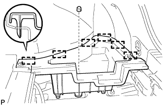
Remove the clip.
-
Disengage the 6 guides and remove the deck floor box RH.
-
- Click here
REMOVE REAR FLOOR BOARD UPPER NO. 3 PLATE
-
Disengage the 4 claws and 2 guides, and remove the rear floor board upper No. 3 plate.
-
- Click here
DISCONNECT CABLE FROM NEGATIVE BATTERY TERMINAL
Note:When disconnecting the cable, some systems need to be initialized after the cable is reconnected (Click here).
- Click here
DISCONNECT FRONT DOOR OPENING TRIM WEATHERSTRIP
Tip:Use the same procedure for the RH and LH side (Click here).
- Click here
REMOVE INSTRUMENT SIDE PANEL
-
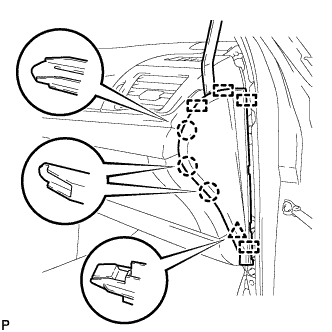
Using a moulding remover, disengage the 3 claws, clip and 4 guides, and remove the instrument side panel RH.
-
Disconnect the connector.
-
- Click here
REMOVE NO. 3 INSTRUMENT CLUSTER FINISH PANEL GARNISH (for Metal Finish Panel and Urethane Panel)
-
Disengage the 5 clips and remove the No. 3 instrument cluster finish panel garnish.
-
- Click here
REMOVE NO. 3 INSTRUMENT CLUSTER FINISH PANEL GARNISH (for Wood Panel and Bamboo Panel)
-
Disengage the 4 clips and remove the No. 3 instrument cluster finish panel garnish.
-
- Click here
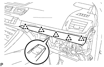
REMOVE LOWER CENTER INSTRUMENT PANEL FINISH PANEL
-
Open the glove compartment door.
-
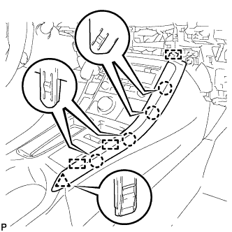
Using a moulding remover, disengage the 7 claws and 4 guides, and remove the lower center instrument panel finish panel as shown in the illustration.
-
- Click here
REMOVE UPPER NO. 2 CONSOLE PANEL GARNISH
-
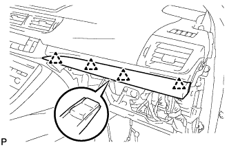
Disengage the 5 claws, clip and 2 guides, and remove the upper No. 2 console panel garnish.
-
- Click here
REMOVE UPPER NO. 1 CONSOLE PANEL GARNISH
-
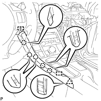
Disengage the 4 claws, clip and 3 guides, and remove the upper No. 1 console panel garnish.
-
- Click here
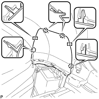
REMOVE UPPER CONSOLE PANEL SUB-ASSEMBLY
-
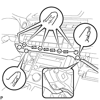
Open the console compartment door.
-
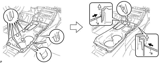
Using a moulding remover, disengage the 9 claws of the vehicle rear side.
Table 1. Text in Illustration *a Protective Tape - - -
Using a screwdriver with its tip wrapped with protective tape, disengage the 3 claws of the vehicle front side as shown in the illustration.
-
Disengage the clamp.
-
Disconnect each connector and remove the upper console panel sub-assembly.
-
- Click here
REMOVE SHIFT LEVER KNOB SUB-ASSEMBLY
-
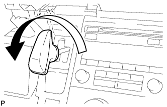
Turn the shift lever knob counterclockwise and remove the shift lever knob sub-assembly.
-
- Click here
REMOVE INTEGRATION CONTROL AND PANEL ASSEMBLY
-
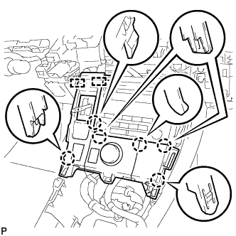
Disengage the 6 claws and 2 guides.
-
Disengage the clamp.
-
Disconnect each connector and remove the integration control and panel assembly.
-
- Click here
REMOVE AIR CONDITIONING CONTROL ASSEMBLY
-
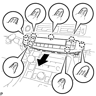
Disengage the 7 claws and remove the air conditioning control assembly as shown in the illustration.
-
Disconnect the connector.
-
- Click here
REMOVE RADIO RECEIVER ASSEMBLY WITH BRACKET
-
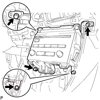
Remove the 4 bolts.
-
Pull the radio receiver assembly with bracket toward the rear of the vehicle.
-
Disconnect each connector and remove the radio receiver assembly with bracket.
-
- Click here
REMOVE DISPLAY AND NAVIGATION MODULE DISPLAY ASSEMBLY WITH BRACKET
-
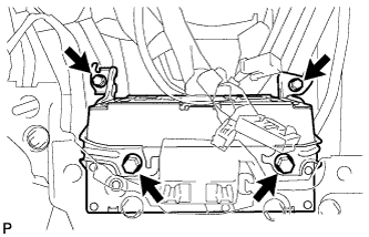
Remove the 4 bolts.
-
Disconnect each connector and remove the display and navigation module display assembly with bracket.
-
- Click here
REMOVE HARD DISK DRIVE (for Two Screw Type)
-
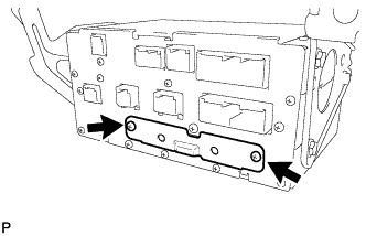
Remove the 2 screws.
-
Using a screwdriver, pull out the hard disk drive in the direction shown by the arrow in the illustration to remove it.
Table 2. Text in Illustration *1 Protective Tape Tip:Tape the screwdriver tip before use.
-
- Click here
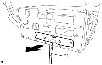
REMOVE HARD DISK DRIVE (for One Screw Type)
-
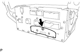
Remove the screw.
-
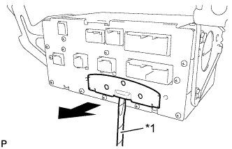
Using a screwdriver, pull out the hard disk drive in the direction shown by the arrow in the illustration to remove it.
Table 3. Text in Illustration *1 Protective Tape Tip:Tape the screwdriver tip before use.
-