G-BOOK SYSTEM, Diagnostic DTC:B15DE
| DTC Code | DTC Name |
|---|---|
| B15DE | Telematics Transceiver Location Data Blackout |
DESCRIPTION
The telematics transceiver checks the reception condition of the location data every minute after the power switch is turned on (ACC). If the location data is not received from the navigation computer sub-assembly for 5 minutes, this DTC will be stored.
| DTC No. | DTC Detection Condition | Trouble Area |
|---|---|---|
| B15DE | Location information from USB communication is interrupted. |
|
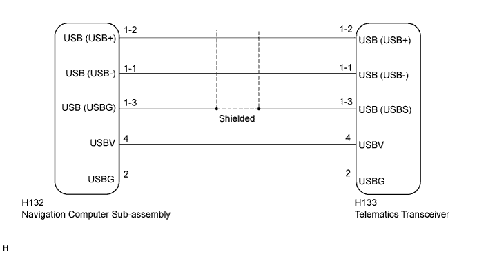
WIRING DIAGRAM
INSPECTION PROCEDURE
Tech Tips
When replacing the navigation computer sub-assembly or telematics transceiver, perform the vehicle contract setting Click here.
PROCEDURE
-
INSPECTION USING "SYSTEM CHECK MODE" SCREEN
-
Perform inspections indicated on the System Check Mode screen to confirm the DCM inspection result Click here.
Result Result Proceed to "OK" is displayed in "DCM" on the System Check Mode screen. A "NCON" is displayed in "DCM" on the System Check Mode screen. B
B 
GO TO INSPECTION PROCEDURE FOR "NCON" IS DISPLAYED IN "DCM" ON THE SYSTEM CHECK MODE SCREEN Click here
A 
-
-
CHECK DTC
-
Clear the DTCs Click here.
-
Recheck for DTCs and check if the same DTC is output again.
Result Result Proceed to B15DE is output A No DTC is output B
B
USE SIMULATION METHOD TO CHECK Click here
A
-
-
CHECK HARNESS AND CONNECTOR (NAVIGATION COMPUTER SUB-ASSEMBLY - TELEMATICS TRANSCEIVER)
-
Check the installation condition.
-
Check the USB communication cable (digital communication cable) between the navigation computer sub-assembly and the telematics transceiver for any installation or connection problems.
-
-
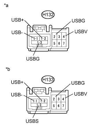
Text in Illustration *a Front view of wire harness connector
(to Navigation Computer Sub-assembly)
*b Front view of wire harness connector
(to Telematics Transceiver)
Disconnect the H132 navigation computer sub-assembly connector.
-
Disconnect the H133 telematics transceiver connector.
-
Measure the resistance according to the value(s) in the table below.
Standard Resistance Tester Connection Condition Specified Condition H132-4 (USBV) - H133-4 (USBV) Always Below 1 Ω H132-2 (USBG) - H133-2 (USBG) Always Below 1 Ω H133-4 (USBV) - Body ground Always 10 kΩ or higher H133-2 (USBG) - Body ground Always 10 kΩ or higher Standard Resistance (USB Cable) Tester Connection Condition Specified Condition H132-1-2 (USB+) - H133-1-2 (USB+) Always Below 1 Ω H132-1-1 (USB-) - H133-1-1 (USB-) Always Below 1 Ω H132-1-3 (USBG) - H133-1-3 (USBS) Always Below 1 Ω H133-1-2 (USB+) - Body ground Always 10 kΩ or higher H133-1-1 (USB-) - Body ground Always 10 kΩ or higher H133-1-3 (USBS) - Body ground Always 10 kΩ or higher
NG
REPAIR OR REPLACE HARNESS OR CONNECTOR
OK
-
-
REPLACE TELEMATICS TRANSCEIVER
-
Replace the telematics transceiver with a known good one and check if the same problem occurs again Click here.
-
Clear the DTCs Click here.
-
Recheck for DTCs and check if the same DTC is output again.
OK No DTCs are output.
-
NG
REPLACE NAVIGATION COMPUTER SUB-ASSEMBLY Click here
OK 
END
-