NAVIGATION SYSTEM (for HDD) Multi-display Switch Circuit
DESCRIPTION
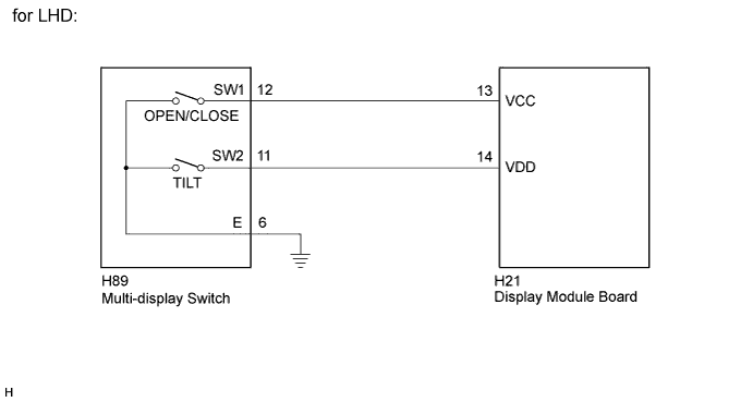
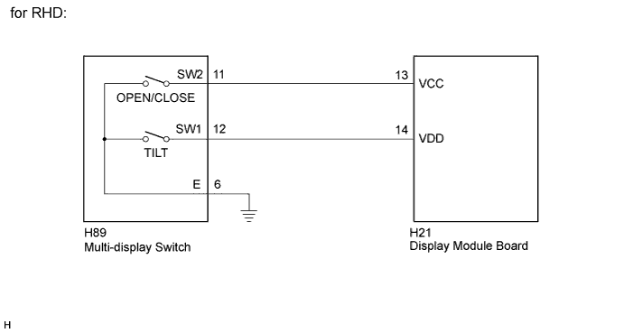
The center instrument cluster finish panel assembly (multi-display) opens, closes and tilts the multi-display according to the operation of the "OPEN/CLOSE" and "TILT" switches of the multi-display switch.
WIRING DIAGRAM
INSPECTION PROCEDURE
PROCEDURE
-
INSPECT MULTI-DISPLAY SWITCH (MULTI-DISPLAY SWITCH)
-
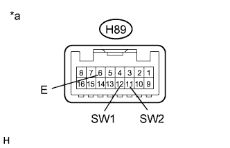
Text in Illustration *a Component without harness connected
(Multi-display Switch)
Disconnect the H89 multi-display switch connector.
-
Measure the resistance according to the value(s) in the table below.
Standard Resistance (for LHD) Tester Connection Condition Specified Condition H89-12 (SW1) - H89-6 (E) "OPEN/CLOSE" switch not pressed 10 kΩ or higher H89-12 (SW1) - H89-6 (E) "OPEN/CLOSE" switch pressed Below 1 Ω H89-11 (SW2) - H89-6 (E) "TILT" switch not pressed 10 kΩ or higher H89-11 (SW2) - H89-6 (E) "TILT" switch pressed Below 1 Ω Standard Resistance (for RHD) Tester Connection Condition Specified Condition H89-11 (SW2) - H89-6 (E) "OPEN/CLOSE" switch not pressed 10 kΩ or higher H89-11 (SW2) - H89-6 (E) "OPEN/CLOSE" switch pressed Below 1 Ω H89-12 (SW1) - H89-6 (E) "TILT" switch not pressed 10 kΩ or higher H89-12 (SW1) - H89-6 (E) "TILT" switch pressed Below 1 Ω
NG 
REPLACE MULTI-DISPLAY SWITCH Click here
OK 
-
-
CHECK HARNESS AND CONNECTOR
-
Disconnect the H89 multi-display switch connector.
-
Disconnect the H21 display module board connector.
-
Measure the resistance according to the value(s) in the table below.
Standard Resistance (for LHD) Tester Connection Condition Specified Condition H89-12 (SW1) - H21-13 (VCC) Always Below 1 Ω H89-11 (SW2) - H21-14 (VDD) Always Below 1 Ω H89-12 (SW1) - Body ground Always 10 kΩ or higher H89-11 (SW2) - Body ground Always 10 kΩ or higher H89-6 (E) - Body ground Always Below 1 Ω Standard Resistance (for RHD) Tester Connection Condition Specified Condition H89-11 (SW2) - H21-13 (VCC) Always Below 1 Ω H89-12 (SW1) - H21-14 (VDD) Always Below 1 Ω H89-11 (SW2) - Body ground Always 10 kΩ or higher H89-12 (SW1) - Body ground Always 10 kΩ or higher H89-6 (E) - Body ground Always Below 1 Ω
NG
REPAIR OR REPLACE HARNESS OR CONNECTOR
OK 
PROCEED TO NEXT SUSPECTED AREA SHOWN IN PROBLEM SYMPTOMS TABLE Click here
-