NAVIGATION SYSTEM (for HDD) Illumination Circuit
DESCRIPTION
Power is supplied to the steering pad switch assembly and multi-display switch illumination when the light control switch is in the tail or head position.
WIRING DIAGRAM
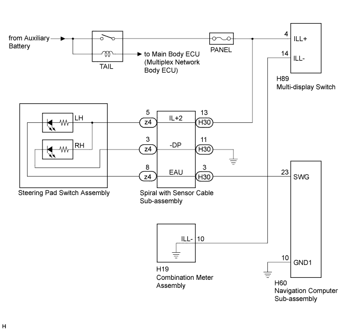
INSPECTION PROCEDURE
Note
-
Inspect the fuse for circuits related to this system before performing the following inspection procedure.
-
The vehicle is equipped with a Supplemental Restraint System (SRS). Before servicing (including removal or installation of parts), be sure to read Precaution for Supplemental Restraint System Click here.
PROCEDURE
-
CHECK ILLUMINATION
-
Check if the illumination for the steering pad switch assembly, multi-display switch, glove box or others (hazard switch, etc.) comes on when the light control switch is turned to the tail or head position.
Result Result Proceed to Illumination comes on for all components except steering pad switch. A Illumination comes on for all components except multi-display switch. B No illumination comes on (steering pad switch assembly, multi-display switch, glove box, hazard switch, etc.). C
B 
INSPECT MULTI-DISPLAY SWITCH (MULTI-DISPLAY SWITCH ILLUMINATION) Click here
C 
GO TO LIGHTING SYSTEM Click here
A 
-
-
CHECK HARNESS AND CONNECTOR (ILLUMINATION SIGNAL)
-
Disconnect the H30 spiral with sensor cable sub-assembly connector.
-
Measure the voltage according to the value(s) in the table below.
Standard Voltage Tester Connection Condition Specified Condition H30-13 (IL+2) - Body ground Light control switch in the tail or head position 11 to 14 V
NG
REPAIR OR REPLACE HARNESS OR CONNECTOR
OK
-
-
INSPECT SPIRAL WITH SENSOR CABLE SUB-ASSEMBLY
-
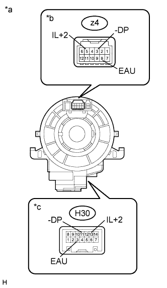
Text in Illustration *a Component without harness connected
(Spiral with Sensor Cable Sub-assembly)
*b Steering Pad Switch Assembly Side *c Vehicle Side Disconnect the z4 steering pad switch assembly and H30 spiral with sensor cable sub-assembly connectors.
-
Measure the resistance according to the value(s) in the table below.
Standard Resistance Tester Connection Condition Specified Condition z4-8 (EAU) - H30-3 (EAU) Center Below 1 Ω 2.5 rotations to the left 2.5 rotations to the right z4-5 (IL+2) - H30-13 (IL+2) Center Below 1 Ω 2.5 rotations to the left 2.5 rotations to the right z4-3 (-DP) - H30-11 (-DP) Center Below 1 Ω 2.5 rotations to the left 2.5 rotations to the right -
After setting the spiral with sensor cable sub-assembly to the center position, rotate the spiral with sensor cable sub-assembly 2.5 times clockwise. Then while rotating the spiral with sensor cable as shown in the table below.
Standard Resistance Tester Connection Condition Specified Condition z4-8 (EAU) - H30-3 (EAU) Always Below 1 Ω z4-5 (IL+2) - H30-13 (IL+2) Always Below 1 Ω z4-3 (-DP) - H30-11 (-DP) Always Below 1 Ω Note
-
The spiral with sensor cable sub-assembly is an important part of the SRS airbag system. Incorrect removal or installation of the spiral with sensor cable sub-assembly may prevent the airbag from deploying. Refer to the pages shown in the brackets.
-
As the spiral with sensor cable may break, do not rotate the spiral with sensor cable sub-assembly more than the specified amount.
-
NG
REPLACE SPIRAL WITH SENSOR CABLE SUB-ASSEMBLY Click here
OK
-
-
CHECK HARNESS AND CONNECTOR
-
Disconnect the H60 display and navigation module display connector.
-
Disconnect the H30 spiral with sensor cable sub-assembly connector.
-
Measure the resistance according to the value(s) in the table below.
Standard Resistance Tester Connection Condition Specified Condition H60-23 (SWG) - H30-3 (EAU) Always Below 1 Ω H30-11 (-DP) - Body ground Always Below 1 Ω H60-23 (SWG) - Body ground Always 10 kΩ or higher
NG
REPAIR OR REPLACE HARNESS OR CONNECTOR
OK
-
-
INSPECT NAVIGATION COMPUTER SUB-ASSEMBLY
-
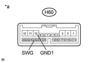
Text in Illustration *a Component without harness connected
(Navigation Computer Sub-assembly)
Disconnect the H60 navigation computer sub-assembly connector.
-
Measure the resistance according to the value(s) in the table below .
Standard Resistance Tester Connection Condition Specified Condition H60-10 (GND1) - H60-23 (SWG) Always Below 1 Ω
NG
REPLACE NAVIGATION COMPUTER SUB-ASSEMBLY Click here
OK
-
-
INSPECT STEERING PAD SWITCH ASSEMBLY
-
Disconnect the z4 steering pad switch assembly connector.
-
Check that the steering pad switch assembly illuminates according to the table below.
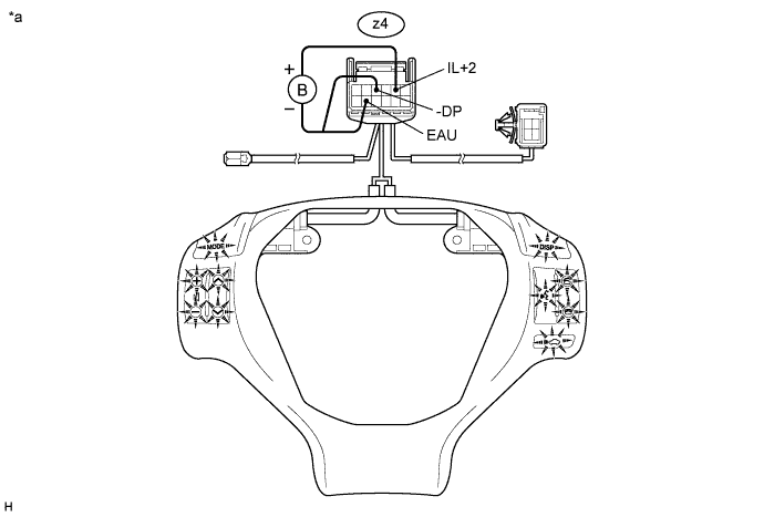
OK Connection Specified Condition Auxiliary battery positive (+) → z4-5 (IL+2)
Auxiliary battery negative (-) → z4-8 (EAU)
Switches of steering pad switch LH side illuminates. Auxiliary battery positive (+) → z4-5 (IL+2)
Auxiliary battery negative (-) → z4-3 (-DP)
Switches of steering pad switch RH side illuminates. Text in Illustration *a Component without harness connected
(Steering Pad Switch Assembly)
- -
NG
REPLACE STEERING PAD SWITCH ASSEMBLY Click here
OK 
PROCEED TO NEXT SUSPECTED AREA SHOWN IN PROBLEM SYMPTOMS TABLE Click here
-
-
INSPECT MULTI-DISPLAY SWITCH (MULTI-DISPLAY SWITCH ILLUMINATION)
-
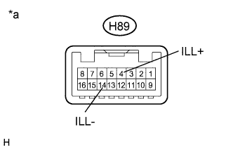
Text in Illustration *a Component without harness connected
(Multi-display Switch)
Disconnect the H89 multi-display switch connector.
-
Connect a positive (+) lead to terminal ILL+ and a negative (-) lead from the auxiliary battery to terminal ILL- of the multi-display switch connector.
-
Check that the multi-display switch illumination comes on.
OK Multi-display switch illumination comes on.
NG
REPLACE MULTI-DISPLAY SWITCH Click here
OK
-
-
CHECK HARNESS AND CONNECTOR (ILLUMINATION SIGNAL)
-
Disconnect the H89 multi-display switch connector.
-
Measure the voltage according to the value(s) in the table below.
Standard Voltage Tester Connection Condition Specified Condition H89-4 (ILL+) - Body ground Light control switch in the tail or head position 11 to 14 V
NG
REPAIR OR REPLACE HARNESS OR CONNECTOR
OK
-
-
CHECK HARNESS AND CONNECTOR
-
Disconnect the H89 multi-display switch connector.
-
Disconnect the H19 combination meter assembly connector.
-
Measure the resistance according to the value(s) in the table below.
Standard Resistance Tester Connection Condition Specified Condition H89-14 (ILL-) - H19-11 (ILL-) Always Below 1 Ω H89-14 (ILL-) - Body ground Always 10 kΩ or higher
NG
REPAIR OR REPLACE HARNESS OR CONNECTOR
OK
GO TO METER / GAUGE SYSTEM Click here
-