NAVIGATION SYSTEM (for HDD) Steering Pad Switch Circuit
DESCRIPTION
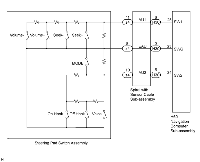
This circuit sends an operation signal from the steering pad switch assembly to the navigation computer sub-assembly.
If there is an open in the circuit, the navigation system cannot be operated using the steering pad switch assembly.
If there is a short in the circuit, the resulting condition is the same as if the switch were continuously pressed. Therefore, the navigation computer sub-assembly cannot be operated using the steering pad switch assembly, and the navigation computer sub-assembly itself cannot function.
WIRING DIAGRAM
INSPECTION PROCEDURE
Note
The vehicle is equipped with a Supplemental Restraint System (SRS). Before servicing (including removal or installation of parts), be sure to read Precaution for Supplemental Restraint System Click here.
PROCEDURE
-
CHECK HARNESS AND CONNECTOR (STEERING PAD SWITCH SIGNAL)
-
Disconnect the H60 navigation computer sub-assembly connector.
-
Measure the resistance according to the value(s) in the table below.
Standard Resistance Tester Connection Switch Condition Specified Condition H60-25 (SW1) - H60-23 (SWG) No switch pushed 95 to 105 kΩ H60-25 (SW1) - H60-23 (SWG) Seek+ switch pushed Below 2.5 Ω H60-25 (SW1) - H60-23 (SWG) Seek- switch pushed 313 to 345 Ω H60-25 (SW1) - H60-23 (SWG) Volume+ switch pushed 950 to 1050 Ω H60-25 (SW1) - H60-23 (SWG) Volume- switch pushed 2955 to 3265 Ω H60-24 (SW2) - H60-23 (SWG) No switch pushed 95 to 105 kΩ H60-24 (SW2) - H60-23 (SWG) MODE switch pushed Below 2.5 Ω H60-24 (SW2) - H60-23 (SWG) Voice switch pushed 2955 to 3265 Ω H60-24 (SW2) - H60-23 (SWG) On Hook switch pushed 323 to 335 Ω H60-24 (SW2) - H60-23 (SWG) Off Hook switch pushed 950 to 1050 Ω
NG 
CHECK HARNESS AND CONNECTOR Click here
OK 
PROCEED TO NEXT SUSPECTED AREA SHOWN IN PROBLEM SYMPTOMS TABLE Click here
-
-
CHECK HARNESS AND CONNECTOR
-
Disconnect the H60 navigation computer sub-assembly connector.
-
Disconnect the H30 spiral with sensor cable sub-assembly connector.
-
Measure the resistance according to the value(s) in the table below.
Standard Resistance Tester Connection Condition Specified Condition H60-25 (SW1) - H30-6 (AU1) Always Below 1 Ω H60-24 (SW2) - H30-5 (AU2) Always Below 1 Ω H60-23 (SWG) - H30-3 (EAU) Always Below 1 Ω H60-25 (SW1) - Body ground Always 10 kΩ or higher H60-24 (SW2) - Body ground Always 10 kΩ or higher H60-23 (SWG) - Body ground Always 10 kΩ or higher
NG 
REPAIR OR REPLACE HARNESS OR CONNECTOR
OK 
-
-
INSPECT SPIRAL WITH SENSOR CABLE SUB-ASSEMBLY
-
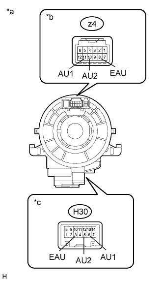
Text in Illustration *a Component without harness connected
(Spiral with Sensor Cable Sub-assembly)
*b Steering Pad Switch Assembly Side *c Vehicle Side Disconnect the z4 steering pad switch assembly and H30 spiral with sensor cable sub-assembly connectors.
-
Measure the resistance according to the value(s) in the table below.
Standard Resistance Tester Connection Condition Specified Condition z4-8 (EAU) - H30-3 (EAU) Center Below 1 Ω 2.5 rotations to the left 2.5 rotations to the right z4-11 (AU1) - H30-6 (AU1) Center Below 1 Ω 2.5 rotations to the left 2.5 rotations to the right z4-10 (AU2) - H30-5 (AU2) Center Below 1 Ω 2.5 rotations to the left 2.5 rotations to the right -
After setting the spiral with sensor cable sub-assembly to the center position, rotate the spiral with sensor cable sub-assembly 2.5 times clockwise. Then while rotating the spiral with sensor cable sub-assembly 5 times counterclockwise, measure the resistance as shown in the table below.
Standard Resistance Tester Connection Condition Specified Condition z4-8 (EAU) - H30-3 (EAU) Always Below 1 Ω z4-11 (AU1) - H30-6 (AU1) Always Below 1 Ω z4-10 (AU2) - H30-5 (AU2) Always Below 1 Ω Note
-
The spiral with sensor cable sub-assembly is an important part of the SRS airbag system. Incorrect removal or installation of the spiral with sensor cable sub-assembly may prevent the airbag from deploying. Refer to the pages shown in the brackets.
-
As the spiral with sensor cable sub-assembly may break, do not rotate the spiral with sensor cable with sensor sub-assembly more than the specified amount.
-
NG
REPLACE SPIRAL WITH SENSOR CABLE SUB-ASSEMBLY Click here
OK
-
-
INSPECT STEERING PAD SWITCH ASSEMBLY
-
Disconnect the z4 steering pad switch assembly connector.
-
Measure the resistance according to the value(s) in the table below.
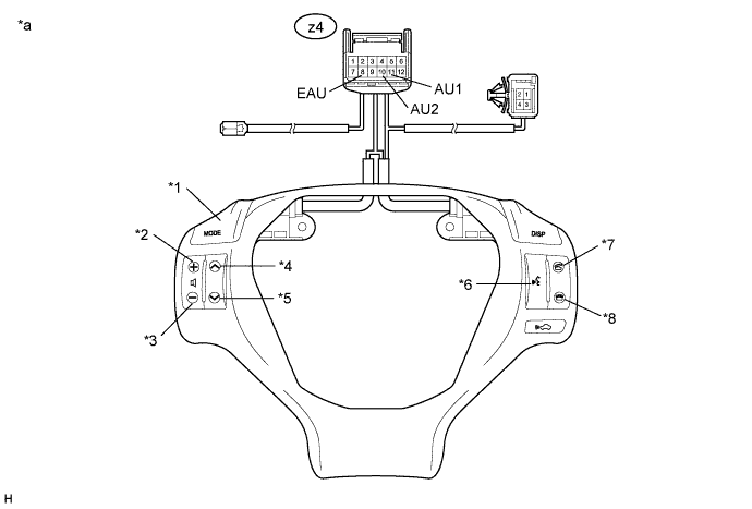
Standard Resistance Tester Connection Switch Condition Specified Condition z4-11 (AU1) - z4-8 (EAU) No switch pushed 95 to 105 kΩ z4-11 (AU1) - z4-8 (EAU) Seek+ switch pushed Below 2.5 Ω z4-11 (AU1) - z4-8 (EAU) Seek- switch pushed 313 to 345 Ω z4-11 (AU1) - z4-8 (EAU) Volume+ switch pushed 950 to 1050 Ω z4-11 (AU1) - z4-8 (EAU) Volume- switch pushed 2955 to 3265 Ω z4-10 (AU2) - z4-8 (EAU) No switch pushed 95 to 105 kΩ z4-10 (AU2) - z4-8 (EAU) MODE switch pushed Below 2.5 Ω z4-10 (AU2) - z4-8 (EAU) Voice switch pushed 2955 to 3265 Ω z4-10 (AU2) - z4-8 (EAU) On Hook switch pushed 323 to 335 Ω z4-10 (AU2) - z4-8 (EAU) Off Hook switch pushed 950 to 1050 Ω Text in Illustration *1 MODE *2 Volume+ *3 Volume- *4 Seek+ *5 Seek- *6 Voice *7 Off Hook *8 On Hook *a Component without harness connected
(Steering Pad Switch Assembly)
- -
NG
REPLACE STEERING PAD SWITCH ASSEMBLY Click here
OK
USE SIMULATION METHOD TO CHECK Click here
-