NAVIGATION SYSTEM AVC-LAN Circuit
DESCRIPTION
Each unit of the navigation system connected to the AVC-LAN (communication bus) transfers the switch signals using the AVC-LAN.
If a short to +B or short to ground occurs in the AVC-LAN, the navigation system will not function normally because communication is not possible.
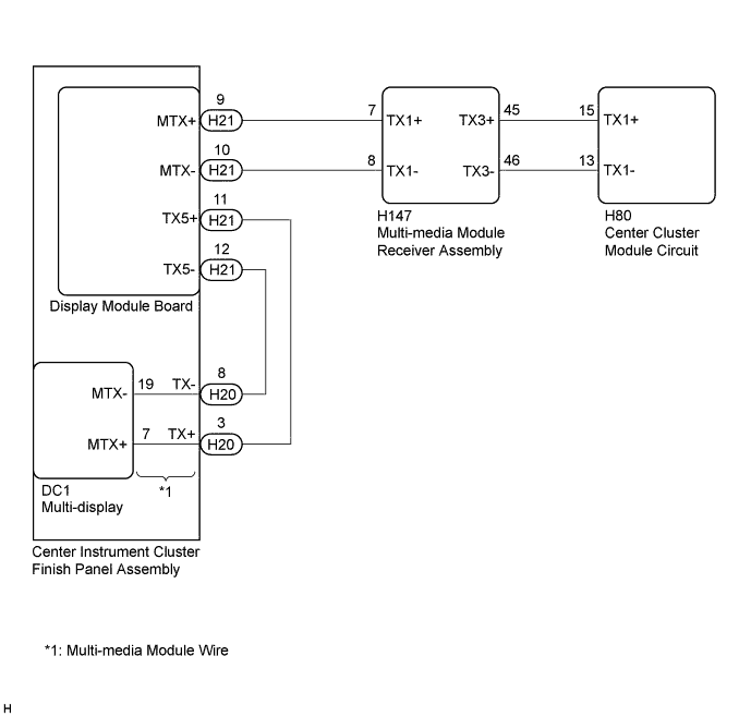
WIRING DIAGRAM
INSPECTION PROCEDURE
Note
Depending on the parts that are replaced during vehicle inspection or maintenance, performing initialization, registration or calibration may be needed. Refer to Precaution for Navigation System Click here.
Tech Tips
The multi-media module receiver assembly is the master unit.
PROCEDURE
-
INSPECT MULTI-MEDIA MODULE RECEIVER ASSEMBLY
-
Remove the multi-media module receiver assembly.
-
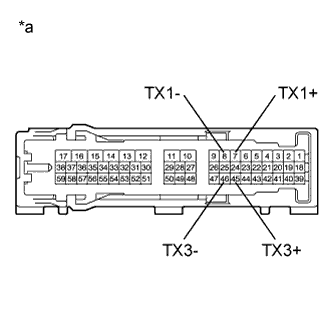
Text in Illustration *a Component without harness connected
(Multi-media Module Receiver Assembly)
Measure the resistance according to the value(s) in the table below.
Standard Resistance Tester Connection Condition Specified Condition 7 (TX1+) - 8 (TX1-) Always 60 to 80 Ω 45 (TX3+) - 46 (TX3-) Always 60 to 80 Ω
NG 
REPLACE MULTI-MEDIA MODULE RECEIVER ASSEMBLY Click here
OK 
-
-
CHECK HARNESS AND CONNECTOR (MULTI-MEDIA MODULE RECEIVER ASSEMBLY - CENTER CLUSTER MODULE CIRCUIT)
-
Disconnect the H147 multi-media module receiver assembly connector.
-
Disconnect the H80 center cluster module circuit connector.
-
Measure the resistance according to the value(s) in the table below.
Standard Resistance Tester Connection Condition Specified Condition H147-45 (TX3+) - H80-15 (TX1+) Always Below 1 Ω H147-46 (TX3-) - H80-13 (TX1-) Always Below 1 Ω H147-45 (TX3+) - Body ground Always 10 kΩ or higher H147-46 (TX3-) - Body ground Always 10 kΩ or higher
NG
REPAIR OR REPLACE HARNESS OR CONNECTOR
OK
-
-
CHECK HARNESS AND CONNECTOR (MULTI-MEDIA MODULE RECEIVER ASSEMBLY - DISPLAY MODULE BOARD)
-
Disconnect the H147 multi-media module receiver assembly connector.
-
Disconnect the H21 display module board connector.
-
Measure the resistance according to the value(s) in the table below.
Standard Resistance Tester Connection Condition Specified Condition H147-7 (TX1+) - H21-9 (MTX+) Always Below 1 Ω H147-8 (TX1-) - H21-10 (MTX-) Always Below 1 Ω H147-7 (TX1+) - Body ground Always 10 kΩ or higher H147-8 (TX1-) - Body ground Always 10 kΩ or higher
NG
REPAIR OR REPLACE HARNESS OR CONNECTOR
OK
-
-
CHECK HARNESS AND CONNECTOR (DISPLAY MODULE BOARD - MULTI-MEDIA MODULE WIRE)
-
Disconnect the H21 display module board connector.
-
Disconnect the H20 multi-media module wire connector.
-
Measure the resistance according to the value(s) in the table below.
Standard Resistance Tester Connection Condition Specified Condition H21-11 (TX5+) - H20-3 (TX+) Always Below 1 Ω H21-12 (TX5-) - H20-8 (TX-) Always Below 1 Ω H21-11 (TX5+) - Body ground Always 10 kΩ or higher H21-12 (TX5-) - Body ground Always 10 kΩ or higher
NG
REPAIR OR REPLACE HARNESS OR CONNECTOR
OK
-
-
INSPECT MULTI-MEDIA MODULE WIRE
-
Remove the multi-media module wire.
-
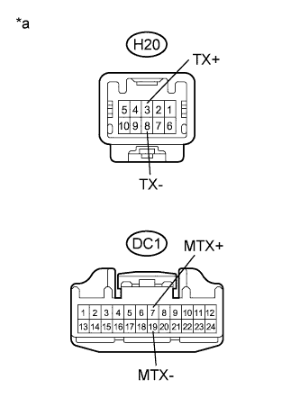
Text in Illustration *a Component without harness connected
(Multi-media Module Wire)
Measure the resistance according to the value(s) in the table below.
Standard Resistance Tester Connection Condition Specified Condition H20-3 (TX+) - DC1-7 (MTX+) Always Below 1 Ω H20-8 (TX-) - DC1-19 (MTX-) Always Below 1 Ω H20-3 (TX+) - Body ground Always 10 kΩ or higher H20-8 (TX-) - Body ground Always 10 kΩ or higher
NG
REPLACE MULTI-MEDIA MODULE WIRE Click here
OK
-
-
INSPECT MALFUNCTIONING PARTS
-
Disconnect and reconnect each slave unit one by one until the master unit returns to normal operation.
Tech Tips
-
Check all slave units.
-
If disconnecting a slave unit causes the master unit to return to normal operation, the slave unit is defective and should be replaced.
OK Master unit returns to normal operation. -
NG
REPLACE MULTI-MEDIA MODULE RECEIVER ASSEMBLY Click here
OK 
REPLACE MALFUNCTIONING PARTS
-