NAVIGATION SYSTEM TERMINALS OF ECU
-
MULTI-MEDIA MODULE RECEIVER ASSEMBLY
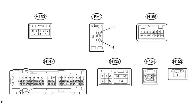
Terminal No. (Symbol) Wiring Color Terminal Description Condition Specified Condition H147-1 (CANH) R CAN communication signal - - H147-2 (CANL) W CAN communication signal - - H147-3 (CNH1) B Local Bus communication signal - - H147-4 (CNL1) W Local Bus communication signal - - H147-7 (TX1+) P AVC-LAN communication signal - - H147-8 (TX1-) G AVC-LAN communication signal - - H147-10 (VMTF) - H147-12 (GND1) GR- W-B Visual mute signal Power switch on (ACC)
Screen display changes
3.5 V or higher
→ Below 1 V
→ 3.5 V or higher
H147-12 (GND1) - Body ground W-B - Body ground Ground Always Below 1 V H147-13 (ILL-) - H147-12 (GND1) B - W-B Illumination signal Light control switch off Below 1 V Light control switch in tail or head position Pulse generation H147-14 (ILL+) - H147-12 (GND1) G - W-B Illumination signal Light control switch off Below 1 V Power switch off
Light control switch in tail or head position
11 to 14 V H147-15 (IG) - H147-12 (GND1) V - W-B Power source (IG) Power switch off Below 1 V Power switch on (IG) 11 to 14 V H147-16 (ACC1) - H147-12 (GND1) B - W-B Power source (ACC) Power switch off Below 1 V Power switch on (ACC) 11 to 14 V H147-17 (+B1) - H147-12 (GND1) V - W-B Power source (+B) Power switch off 11 to 14 V H147-18 (V+) - H147-12 (GND1) R - W-B Video signal Power switch on (IG)
Shift lever in R
Camera lens not covered, displaying an image
Pulse generation (Refer to waveform 1) Power switch on (IG)
Shift lever in R
Camera lens covered, blacking out screen
Pulse generation (Refer to waveform 2) H147-19 (V-) - H147-12 (GND1) W - W-B Ground Always Below 1 V H147-27 (MIN+) - H147-12 (GND1) G*1, W*2 - W-B Microphone voice signal See "Microphone & Voice Recognition Check" in Operation Check Click here
- H147-28 (SGND) - Body ground Shield - Body ground Shield ground Always Below 1 V H147-29 (MACC) - H147-12 (GND1)*2 B - W-B Microphone power supply Power switch off Below 1 V Power switch on (ACC) 4 to 6 V H147-30 (SW1) - H147-32 (SWG) GR - W Steering pad switch signal No switch pushed 2.97 to 3.56 V Seek+ switch pushed 0.27 to 0.35 V Seek- switch pushed 0.86 to 1.03 V Volume+ switch pushed 1.51 to 1.79 V Volume- switch pushed 2.22 to 2.66 V H147-31 (SW2) - H147-32 (SWG) G - W Steering pad switch signal No switch pushed 2.97 to 3.56 V MODE switch pushed 0.27 to 0.35 V On hook switch pushed 0.86 to 1.03 V Off hook switch pushed 1.51 to 1.79 V Voice switch pushed 2.22 to 2.66 V H147-32 (SWG) - Body ground W - Body ground Steering pad switch signal Always Below 1 V H147-39 (CA+) - H147-12 (GND1) B - W-B Television camera power supply Power switch on (IG)
Shift lever in R
5.5 to 7.05 V H147-40 (CGND) - Body ground Shield - Body ground Shield ground Always Below 1 V H147-45 (TX3+) R AVC-LAN communication signal - - H147-46 (TX3-) L AVC-LAN communication signal - - H147-48 (MIN-) - Body ground R - Body ground Microphone voice signal See "Microphone & Voice Recognition Check" in Operation Check Click here
- H147-49 (SNS2) - H147-12 (GND1) V - W-B Microphone connection detection signal Always Below 1 V H147-55 (PKB) - H147-12 (GND1) R - W-B Parking brake signal See "Vehicle Signal Check Mode" in Operation Check Click here
- H147-56 (SPD) - H147-12 (GND1) V - W-B Vehicle speed signal See "Vehicle Signal Check Mode" in Operation Check Click here
- H155-5 (AGND) - Body ground W - Body ground Shield ground Always Below 1 V H155-7 (VAR+) - H155-15 (VA-) W - W Sound signal (Right) External device system playing (when stereo jack used) A waveform synchronized with sounds is output H155-8 (VAL-) - H155-15 (VA-) W - W Sound signal (Left) External device system playing (when stereo jack used) A waveform synchronized with sounds is output H155-15 (VA-) - H147-12 (GND1) W - W-B Sound signal ground Always Below 1 V H155-16 (ADPG) - H147-12 (GND1) W - W-B External device connection detection signal External device connected Below 1 V External device not connected 2.1 to 3 V H150-1 (WUO) W MOST communication wake-up signal - - H150-2 (MI+) B MOST communication signal - - H150-3 (MI-) B MOST communication signal - - H150-4 (SLDI) B Shield ground - - H150-5 (MO+) B MOST communication signal - - H150-6 (MO-) B MOST communication signal - - H150-7 (SLDO) B Shield ground - - H132-1-1 (USB-)*1 B USB communication line - - H132-1-2 (USB+)*1 B USB communication line - - H132-1-3 (USBS) - Body ground*1 B - Body ground Shield ground Always Below 1 V H132-2 (USBG) - Body ground*1 W - Body ground Ground Always Below 1 V H132-3 (VOT+) - H147-12 (GND1)*1 W - W-B Sent voice signal Calling while using the operator service A waveform synchronized with the sent voice is output. H132-4 (USBV) - H147-12 (GND1)*1 W - W-B Telematics transceiver power supply Power switch off A waveform synchronized with the sent voice is output. Power switch on (ACC) 4.75 to 5.25 V H132-5 (VOT-) - H147-12 (GND1)*1 R - W-B Sent voice signal Calling while using the operator service A waveform synchronized with the sent voice is output. H132-6 (VOR-) - H147-12 (GND1)*1 B - W-B Receive voice signal Receiving a call while using the operator service A waveform synchronized with the sent voice is output. H132-7 (VOR+) - H147-12 (GND1)*1 G - W-B Receive voice signal Receiving a call while using the operator service A waveform synchronized with the sent voice is output. H154-1 (USV1) - Power source - - H154-2 (US1-) - Data signal - - H154-3 (US1+) - Data signal - - H154-4 (UGD1) - Ground - - H154-5 (USG1) - Shield ground - - H152-1 (GVIF) B Video signal (Digital) - - RA-5 (ANT+) - H147-12 (GND1) - - W-B Power source of antenna Power switch on (ACC)
Radio switch on and AM or FM selected
11 to 14 V
-
*1: w/ Telematics Transceiver
-
*2: w/o Telematics Transceiver
-
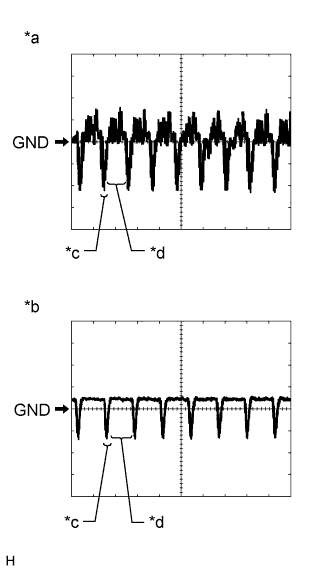
Text in Illustration *a Waveform 1 (camera lens not covered, displaying an image) *b Waveform 2 (camera lens covered, blacking out the screen) *c Synchronization Signal *d Video Waveform Reference (Oscilloscope waveform):
-
Waveform 1 (camera lens is not covered, displaying an image)
Item Content Measurement terminal H147-18 (V+) - H147-12 (GND1) Measurement setting 200 mV/DIV., 50 μsec./DIV. Condition Power switch on (IG), Shift lever in R Tech Tips
The video waveform changes according to the image sent by the television camera assembly.
-
Waveform 2 (camera lens is covered, blacking out the screen)
Item Content Measurement terminal H147-18 (V+) - H147-12 (GND1) Measurement setting 200 mV/DIV., 50 μsec./DIV. Condition Power switch on (IG), Shift lever in R Tech Tips
The video waveform changes according to the image sent by the rear television camera assembly.
-
-
-
STEREO COMPONENT AMPLIFIER ASSEMBLY (for 13 Speakers)
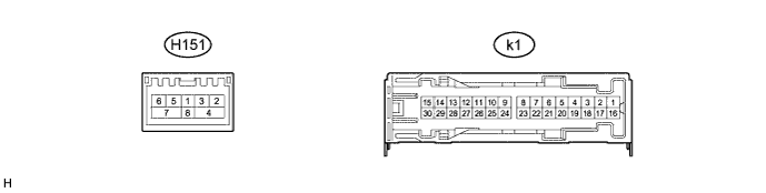
Terminal No. (Symbol) Wiring Color Terminal Description Condition Specification k1-1 (+B) - k1-3 (GND) R - W-B Power source (+B) Power switch off 11 to 14 V k1-2 (TMUT) - Body ground*1 L - Body ground Mute signal Audio system playing Above 3.5 V Emergency call mode Below 1 V k1-3 (GND) - Body ground W-B - Body ground Ground Always Below 1 V k1-5 (WF2+) - k1-3 (GND) Y - W-B Sound signal (Woofer) Audio system playing A waveform synchronized with sounds is output k1-6 (WF1+) - k1-3 (GND) V - W-B Sound signal (Woofer) Audio system playing A waveform synchronized with sounds is output k1-7 (CTR+) - k1-3 (GND) R - W-B Sound signal (Front Center) Audio system playing A waveform synchronized with sounds is output k1-10 (ML+) - k1-3 (GND) R - W-B Sound signal (Front Left) Audio system playing A waveform synchronized with sounds is output k1-11 (MR+) - k1-3 (GND) LG - W-B Sound signal (Front Right) Audio system playing A waveform synchronized with sounds is output k1-12 (FL+) - k1-3 (GND) R - W-B Sound signal (Front Left) Audio system playing A waveform synchronized with sounds is output k1-13 (FR+) - k1-3 (GND) G - W-B Sound signal (Front Right) Audio system playing A waveform synchronized with sounds is output k1-14 (RL+) - k1-3 (GND) G - W-B Sound signal (Rear Left) Audio system playing A waveform synchronized with sounds is output k1-15 (RR+) - k1-3 (GND) R - W-B Sound signal (Rear Right) Audio system playing A waveform synchronized with sounds is output k1-16 (+B2) - k1-3 (GND) B - W-B Power source (+B) Power switch off 11 to 14 V k1-17 (SPD) - k1-3 (GND) V - W-B Vehicle speed signal Power switch on (IG)
Wheel being rotated
Pulse generation k1-18 (GND2) - Body ground W-B - Body ground Ground Always Below 1 V k1-22 (CTR-) - k1-3 (GND) W - W-B Sound signal (Front Center) Audio system playing A waveform synchronized with sounds is output k1-25 (ML-) - k1-3 (GND) W - W-B Sound signal (Front Left) Audio system playing A waveform synchronized with sounds is output k1-26 (MR-) - k1-3 (GND) L - W-B Sound signal (Front Right) Audio system playing A waveform synchronized with sounds is output k1-27 (FL-) - k1-3 (GND) W - W-B Sound signal (Front Left) Audio system playing A waveform synchronized with sounds is output k1-28 (FR-) - k1-3 (GND) BR - W-B Sound signal (Front Right) Audio system playing A waveform synchronized with sounds is output k1-29 (RL-) - k1-3 (GND) BR - W-B Sound signal (Rear Left) Audio system playing A waveform synchronized with sounds is output k1-30 (RR-) - k1-3 (GND) W - W-B Sound signal (Rear Right) Audio system playing A waveform synchronized with sounds is output H151-2 (MI+) B MOST communication signal - - H151-3 (MI-) B MOST communication signal - - H151-4 (SLDI) B Shield ground - - H151-5 (MO+) B MOST communication signal - - H151-6 (MO-) B MOST communication signal - - H151-7 (SLDO) B Shield ground - - H151-8 (WUI) W MOST communication wake-up signal - -
-
*1: w/ Telematics Transceiver
-
-
STEREO COMPONENT AMPLIFIER ASSEMBLY (for 10 Speakers)
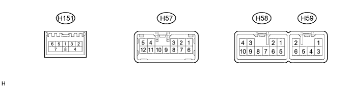
Terminal No. (Symbol) Wiring Color Terminal Description Condition Specification H151-2 (MI+) B MOST communication signal - - H151-3 (MI-) B MOST communication signal - - H151-4 (SLDI) B Shield ground - - H151-5 (MO+) B MOST communication signal - - H151-6 (MO-) B MOST communication signal - - H151-7 (SLDO) B Shield ground - - H151-8 (WUI) W MOST communication wake-up signal - - H57-3 (FL+) - H59-2 (GND) R - W-B Sound signal (Front Left) Audio system playing A waveform synchronized with sounds is output H57-4 (RL+) - H59-2 (GND) G - W-B Sound signal (Rear Left) Audio system playing A waveform synchronized with sounds is output H57-5 (RR+) - H59-2 (GND) R - W-B Sound signal (Rear Right) Audio system playing A waveform synchronized with sounds is output H57-8 (FL-) - H59-2 (GND) W - W-B Sound signal (Front Left) Audio system playing A waveform synchronized with sounds is output H57-9 (FR-) - H59-2 (GND) BR - W-B Sound signal (Front Right) Audio system playing A waveform synchronized with sounds is output H57-10 (FR+) - H59-2 (GND) G - W-B Sound signal (Front Right) Audio system playing A waveform synchronized with sounds is output H57-11 (RL-) - H59-2 (GND) BR - W-B Sound signal (Rear Left) Audio system playing A waveform synchronized with sounds is output H57-12 (RR-) - H59-2 (GND) W - W-B Sound signal (Rear Right) Audio system playing A waveform synchronized with sounds is output H58-1 (WF1+) - H59-2 (GND) V - W-B Sound signal (Woofer) Audio system playing A waveform synchronized with sounds is output H58-2 (WF2+) - H59-2 (GND) Y - W-B Sound signal (Woofer) Audio system playing A waveform synchronized with sounds is output H58-3 (ML+) - H59-2 (GND) P - W-B Sound signal (Front Left) Audio system playing A waveform synchronized with sounds is output H58-4 (MR+) - H59-2 (GND) LG - W-B Sound signal (Front Right) Audio system playing A waveform synchronized with sounds is output H58-5 (TMUT) - H59-2 (GND)*1 L - W-B Mute signal Audio system playing Above 3.5 V Emergency call mode Below 1 V H58-6 (SPD) - H59-2 (GND) V - W-B Vehicle speed signal Power switch on (IG)
Wheel being rotated
Pulse generation H58-7 (CTR-) - H59-2 (GND) W - W-B Sound signal (Front Center) Audio system playing A waveform synchronized with sounds is output H58-8 (CTR+) - H59-2 (GND) R - W-B Sound signal (Front Center) Audio system playing A waveform synchronized with sounds is output H58-9 (ML-) - H59-2 (GND) V - W-B Sound signal (Front Left) Audio system playing A waveform synchronized with sounds is output H58-10 (MR-) - H59-2 (GND) L - W-B Sound signal (Front Right) Audio system playing A waveform synchronized with sounds is output H59-1 (+B) - H59-2 (GND) R - W-B Power source (+B) Power switch off 11 to 14 V H59-2 (GND) - Body ground W-B - Body ground Ground Always Below 1 V H59-3 (+B2) - H59-2 (GND) B - W-B Power source (+B) Power switch off 11 to 14 V H59-6 (GND2) - Body ground W-B - Body ground Ground Always Below 1 V
-
*1: w/ Telematics Transceiver
-
-
CENTER INSTRUMENT CLUSTER FINISH PANEL ASSEMBLY (MULTI-DISPLAY)

Terminal No. (Symbol) Wiring Color Terminal Description Condition Specified Condition H20-3 (TX+) V AVC-LAN communication signal - - H20-4 (ILL) - H20-6 (GND1) G - W-B Illumination signal Light control switch off Below 1 V Power switch off
Light control switch in tail or head position
11 to 14 V H20-5 (+B) - H20-6 (GND1) P - W-B Power source (+B) Power switch off 11 to 14 V H20-6 (GND1) - Body ground W-B - Body ground Ground Always Below 1 V H20-7 (SGN1) - H20-6 (GND1) R - W-B Ground Always Below 1 V H20-8 (TX-) P AVC-LAN communication signal - - H20-9 (VMTI) - H20-6 (GND1) GR - W-B Visual mute signal Power switch on (ACC)
Screen display changes
3.5 V or higher
→ Below 1 V
→ 3.5 V or higher
H20-10 (ACC) - H20-6 (GND1) R - W-B Power source (ACC) Power switch off Below 1 V Power switch on (ACC) 11 to 14 V H153-1 (GVIF) B Video signal (Digital) - - -
MULTI-DISPLAY
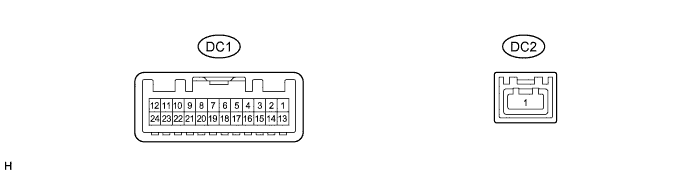
Terminal No. (Symbol) Wiring Color Terminal Description Condition Specification DC1-2 (ILL) - DC1-13 (GND1) G - W-B Illumination signal Light control switch off Below 1 V Power switch off
Light control switch in tail or head position
11 to 14 V DC1-7 (MTX+) P AVC-LAN communication signal - - DC1-11 (VMTI) - DC1-13 (GND1) L - W-B Visual mute signal Power switch on (ACC)
Screen display changes
3.5 V or higher
→ Below 1 V
→ 3.5 V or higher
DC1-12 (+B2) - DC1-13 (GND1) R - W-B Power source (+B) Power switch off 11 to 14 V DC1-13 (GND1) - Body ground W-B - Body ground Ground Always Below 1 V DC1-19 (MTX-) V AVC-LAN communication signal - - DC1-24 (ACC) - DC1-13 (GND1) Y - W-B Power source (ACC) Power switch off Below 1 V Power switch on (ACC) 11 to 14 V DC2-1 (GVIF) B Video signal (Digital) - - -
DISPLAY MODULE BOARD

Terminal No. (Symbol) Wiring Color Terminal Description Condition Specified Condition H21-1 (+B2) - H21-3 (SGND) G - W-B Power source (+B) Power switch off 11 to 14 V H21-2 (ACC2) - H21-3 (SGND) B - W-B Power source (ACC) Power switch off Below 1 V Power switch on (ACC) 11 to 14 V H21-3 (SGND) - Body ground W-B - Body ground Ground Always Below 1 V H21-9 (MTX+) P AVC-LAN communication signal - - H21-10 (MTX-) G AVC-LAN communication signal - - H21-11 (TX5+) V AVC-LAN communication signal - - H21-12 (TX5-) P AVC-LAN communication signal - - H21-13 (VCC) - H20-6 (GND1) G - W-B Multi-display open/close switch signal Power switch on (IG)
Multi-display open/close switch off → on
4.9 V or higher → Below 1.5 V H21-14 (VDD) - H20-6 (GND1) L - W-B Multi-display tilt switch signal Power switch on (IG)
Multi-display tilt switch off → on
4.9 V or higher → Below 1.5 V -
REMOTE TOUCH

Terminal No. (Symbol) Wiring Color Terminal Description Condition Specified Condition H148-1 (+B) - H148-15 (GND) R - W-B Power source (+B) Power switch off 11 to 14 V H148-2 (ACC) - H148-15 (GND) R - W-B Power source (ACC) Power switch off Below 1 V Power switch on (ACC) 11 to 14 V H148-4 (MO-) W Local bus communication signal - - H148-5 (MO+) B Local bus communication signal - - H148-9 (ILL+) - H148-15 (GND) G - W-B Illumination signal Light control switch off Below 1 V Power switch off
Light control switch in tail or head position
11 to 14 V H148-15 (GND) - Body ground W-B - Body ground Ground Always Below 1 V H148-16 (ILL-) - H148-15 (GND) BR - W-B Illumination signal Light control switch off Below 1 V Light control switch in tail or head position Pulse generation -
TELEMATICS TRANSCEIVER (w/ Telematics Transceiver) Click here