STEERING COLUMN ASSEMBLY INSTALLATION
Note
-
Do not replace the spiral cable with the auxiliary battery connected and the power switch on (IG).
-
Do not rotate the spiral cable without the steering wheel with the auxiliary battery connected and the power switch on (IG).
-
Ensure that the steering wheel is installed and aligned straight when inspecting the steering sensor.
-
Do not remove the steering sensor from the spiral cable.
-
INSPECT STEERING COLUMN ASSEMBLY
-
Inspect the bushings.
-
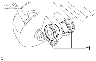
Text in Illustration *1 Bushing Check that the 2 bushings are securely installed to the steering column assembly.
If the 2 bushings are installed improperly, replace the steering column assembly with a new one.
-
Check the 2 bushings for deformation and damage.
If the bushings are deformed or damaged, replace the steering column assembly with a new one.
-
-
Inspect the capsules.
-
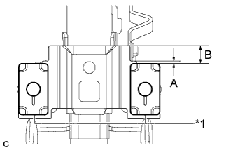
Text in Illustration *1 Capsule Check that the 2 capsules are securely installed to the steering column assembly as shown in the illustration.
Standard Dimension A B 2 mm (0.0787 in.) 17 mm (0.669 in.) If the capsules are not positioned as specified, replace the steering column assembly with a new one.
-
Check the 2 capsules for deformation and damage.
If either of the capsules is deformed, loose, missing or damaged, replace the steering column assembly with a new one.
-
-
-
INSTALL NO. 2 STEERING INTERMEDIATE SHAFT ASSEMBLY
-
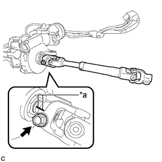
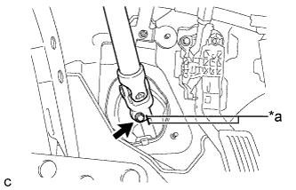
Text in Illustration *a Matchmark Align the matchmarks on the No. 2 steering intermediate shaft assembly and steering column assembly to install the No. 2 steering intermediate shaft assembly.
-
Install the bolt.
- Torque:
- 35 N*m { 357 kgf*cm, 26 ft.*lbf }
-
-
ALIGN FRONT WHEELS FACING STRAIGHT AHEAD
-
INSTALL STEERING POST ASSEMBLY (for LHD)
-
Install the steering post assembly with the bolt and 2 nuts.
- Torque:
- Bolt
- 36 N*m { 367 kgf*cm, 27 ft.*lbf }
- Nut
- 25 N*m { 255 kgf*cm, 18 ft.*lbf }
-
Engage the wire harness clamps to the steering post assembly.
-
Engage the 2 wire harness clamps.
-
Connect the connector to the power steering ECU assembly.
-
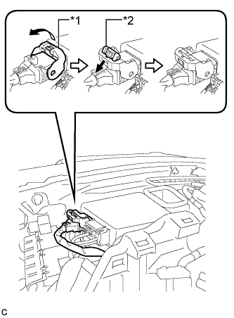
Text in Illustration *1 Lock Lever *2 Lock of Lock Lever Connect the connector to the power steering ECU assembly.
Tech Tips
As shown in the illustration, return the lock lever to its original position to connect the connector and securely push in the lock of the lock lever.
-
-
INSTALL STEERING POST ASSEMBLY (for RHD)
-
Install the steering post assembly with the bolt and 2 nuts.
- Torque:
- Bolt
- 36 N*m { 367 kgf*cm, 27 ft.*lbf }
- Nut
- 25 N*m { 255 kgf*cm, 18 ft.*lbf }
-
Engage the wire harness clamps to the steering post assembly.
-
Engage the 2 wire harness clamps.
-
-
CONNECT NO. 2 STEERING INTERMEDIATE SHAFT ASSEMBLY
-
Text in Illustration *a Matchmark Align the matchmarks on the No. 2 steering intermediate shaft assembly and steering intermediate shaft to connect the No. 2 steering intermediate shaft assembly to the steering intermediate shaft.
-
Install the bolt.
- Torque:
- 35 N*m { 357 kgf*cm, 26 ft.*lbf }
-
-
INSTALL COLUMN HOLE COVER SILENCER SHEET
-
Install the column hole cover silencer sheet with the 2 clips.
-
Install the floor carpet.
-
-
INSTALL NO. 1 AIR DUCT SUB-ASSEMBLY (for LHD)
-
Engage the 2 claws to install the No. 1 air duct sub-assembly.
-
-
INSTALL STOP LIGHT SWITCH ASSEMBLY (for LHD)
-
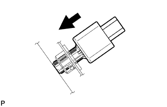
Insert the stop light switch assembly until the rod hits the pedal.
Note
When inserting the stop light switch assembly, support the pedal from behind so that the pedal is not pushed in.
-
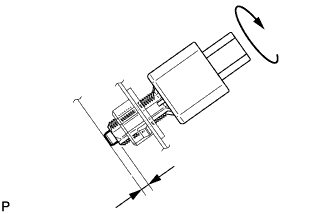
Make a quarter turn clockwise to install the stop light switch assembly.
- Torque:
- 1.5 N*m { 15 kgf*cm, 13 in.*lbf, or less }
Note
When inserting the stop light switch assembly, support the pedal from behind so that the pedal is not pushed in.
-
Connect the connector.
-
Check the protrusion of the rod.
Protrusion of the rod 1.5 to 2.5 mm (0.0591 to 0.0984 in.) If the protrusion is not as specified, adjust it.
Note
Do not depress the brake pedal.
-
-
INSTALL LOWER NO. 1 INSTRUMENT PANEL AIRBAG ASSEMBLY (for LHD)
-
INSTALL UPPER INSTRUMENT PANEL ASSEMBLY (for LHD)
-
INSTALL NO. 2 AIR DUCT SUB-ASSEMBLY (for RHD)
-
Engage the 2 claws to install the No. 2 air duct sub-assembly.
-
-
INSTALL BRAKE PEDAL SUPPORT ASSEMBLY (for RHD)
-
INSTALL TURN SIGNAL SWITCH ASSEMBLY WITH SPIRAL CABLE SUB-ASSEMBLY
Note
-
Do not replace the spiral cable with the auxiliary battery connected and the power switch on (IG).
-
Do not rotate the spiral cable without the steering wheel with the auxiliary battery connected and the power switch on (IG).
-
Ensure that the steering wheel is installed and aligned straight when inspecting the steering sensor.
-
Do not remove the steering sensor from the spiral cable.
-
Using pliers, expand the clamp.
-
While holding the clamp expanded, install the turn signal switch assembly with spiral cable sub-assembly to the steering post assembly and engage the claw.
-
Return the clamp to its original position.
-
Connect the connectors to the turn signal switch assembly with spiral cable sub-assembly.
-
-
INSTALL STEERING COLUMN COVER
Note
If the steering column cover is installed in the incorrect order, it will not be possible to assemble the steering column cover.
-
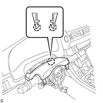
Engage the 2 claws to install the steering column cover (upper side).
-
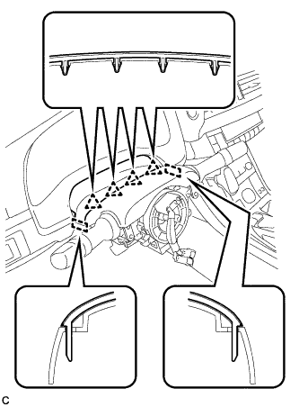
Engage the 4 clips and 2 guides to the steering column cover (upper side).
-
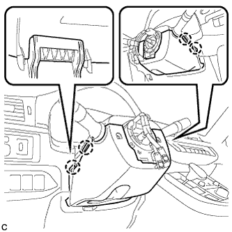
Engage the 4 claws to install the steering column cover (lower side).
-
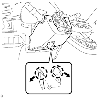
Engage the 2 claws.
Tech Tips
Spread the claws and press the area around the claws to engage them.
-
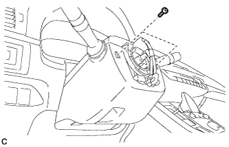
Install the 2 screws.
- Torque:
- 2.0 N*m { 20 kgf*cm, 18 in.*lbf }
-
-
ALIGN FRONT WHEELS FACING STRAIGHT AHEAD
-
ADJUST SPIRAL CABLE WITH SENSOR SUB-ASSEMBLY
Note
Do not adjust the spiral cable with the auxiliary battery connected and the power switch on (IG).
-
Check that the power switch is off.
-
Check that the cable is disconnected from the negative (-) auxiliary battery terminal.
CAUTION:
Wait at least 90 seconds after disconnecting the cable from the negative (-) auxiliary battery terminal to disable the SRS system.
-
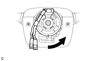
Rotate the spiral cable counterclockwise slowly by hand until it stops.
Note
Do not turn the spiral cable using the airbag wire harness.
-
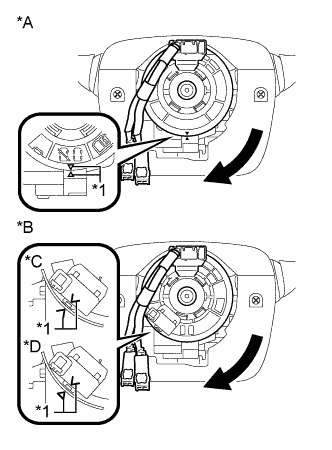
Text in Illustration *A w/o Steering Heater *B w/ Steering Heater *C Type A *D Type B *1 Alignment Mark Rotate the spiral cable clockwise approximately 2.5 turns to align the marks.
Note
Do not turn the spiral cable using the airbag wire harness.
Tech Tips
The spiral cable will rotate approximately 2.5 turns to both the left and right from the center.
-
-
INSTALL STEERING WHEEL ASSEMBLY
-
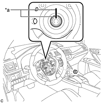
Text in Illustration *a Matchmark Install the steering wheel assembly aligning the matchmarks on the steering wheel assembly and steering main shaft.
-
Install the steering wheel assembly set nut.
- Torque:
- 50 N*m { 510 kgf*cm, 37 ft.*lbf }
-
Connect the connectors to the spiral cable and steering wheel assembly.
-
-
CHECK STEERING WHEEL CENTER POINT
-
INSTALL HORN BUTTON ASSEMBLY
-
ROTATION ANGLE SENSOR VALUE INITIALIZATION AND TORQUE SENSOR ZERO POINT CALIBRATION