STEERING COLUMN ASSEMBLY REMOVAL

Note
-
Do not replace the spiral cable with the auxiliary battery connected and the power switch on (IG).
-
Do not rotate the spiral cable without the steering wheel with the auxiliary battery connected and the power switch on (IG).
-
Ensure that the steering wheel is installed and aligned straight when inspecting the steering sensor.
-
Do not remove the steering sensor from the spiral cable.
-
ALIGN FRONT WHEELS FACING STRAIGHT AHEAD
-
REMOVE HORN BUTTON ASSEMBLY
-
REMOVE STEERING WHEEL ASSEMBLY
-
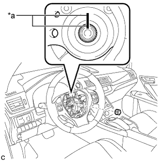
Text in Illustration *a Matchmark Remove the steering wheel assembly set nut.
-
Put matchmarks on the steering wheel assembly and steering main shaft.
-
Disconnect the connectors from the spiral cable and steering wheel assembly.
-
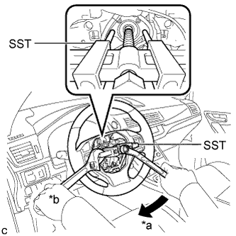
Text in Illustration *a Turn *b Hold Using SST, remove the steering wheel assembly.
- SST
- 09950-50013 ( 09951-05010, 09952-05010, 09953-05020, 09955-04071 )
Note
Apply a small amount of grease to the threads and tip of SST (09953-05020) before use.
-
-
REMOVE STEERING COLUMN COVER
Note
Removing the steering column cover in the incorrect order will cause the parts to break.
-
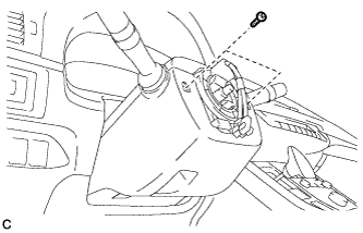
Remove the 2 screws.
-
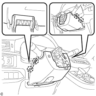
Push the right and left sides of the steering column cover (lower side) to disengage the 4 claws.
-
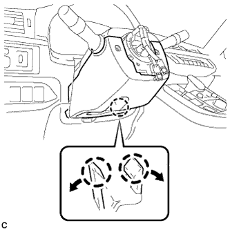
Insert fingers into the opening of the tilt lever of the steering column cover (lower side) to disengage the 2 claws and remove the steering column cover (lower side).
Tech Tips
Spread the claws to disengage them.
-
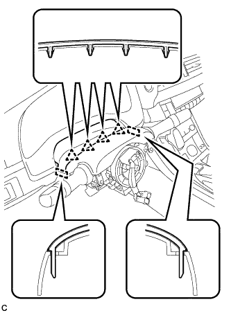
Disengage the 4 clips and 2 guides from the steering column cover (upper side).
-
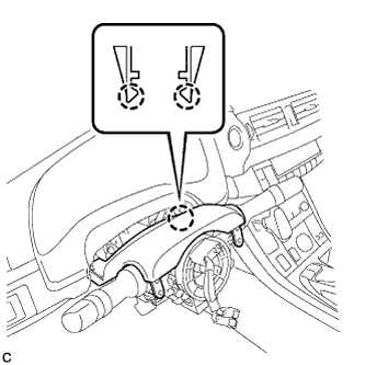
Disengage the 2 claws to remove the steering column cover (upper side).
-
-
REMOVE TURN SIGNAL SWITCH ASSEMBLY WITH SPIRAL CABLE SUB-ASSEMBLY
Note
-
Do not replace the spiral cable with the auxiliary battery connected and the power switch on (IG).
-
Do not rotate the spiral cable without the steering wheel with the auxiliary battery connected and the power switch on (IG).
-
Ensure that the steering wheel is installed and aligned straight when inspecting the steering sensor.
-
Do not remove the steering sensor from the spiral cable.
-
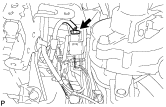
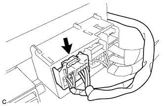
Disconnect the connectors from the turn signal switch assembly with spiral cable sub-assembly.
-
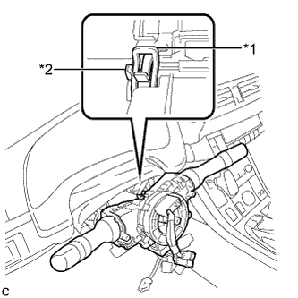
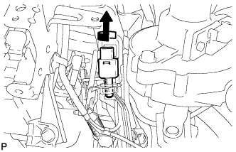
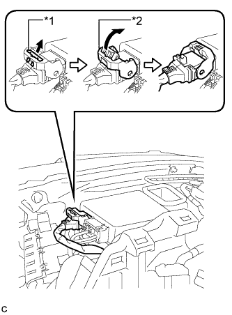
Text in Illustration *1 Clamp *2 Claw Using pliers, expand the clamp.
-
While holding the clamp expanded, raise the claw using a screwdriver to disengage it, and then remove the turn signal switch assembly with spiral cable sub-assembly from the steering post assembly.
-
-
REMOVE UPPER INSTRUMENT PANEL ASSEMBLY (for LHD)
-
REMOVE LOWER NO. 1 INSTRUMENT PANEL AIRBAG ASSEMBLY (for LHD)
-
REMOVE STOP LIGHT SWITCH ASSEMBLY (for LHD)
-
Disconnect the connector.
-
Turn the stop light switch assembly counterclockwise and remove it.
-
-
REMOVE NO. 1 AIR DUCT SUB-ASSEMBLY (for LHD)
-
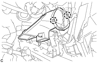
Disengage the 2 claws to remove the No. 1 air duct sub-assembly.
-
-
REMOVE BRAKE PEDAL SUPPORT ASSEMBLY (for RHD)
-
REMOVE NO. 2 AIR DUCT SUB-ASSEMBLY (for RHD)
-
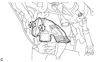
Disengage the 2 claws to remove the No. 2 air duct sub-assembly.
-
-
REMOVE COLUMN HOLE COVER SILENCER SHEET
-
Turn back the floor carpet.
-
Remove the 2 clips and column hole cover silencer sheet.
-
-
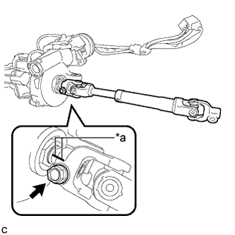
SEPARATE NO. 2 STEERING INTERMEDIATE SHAFT ASSEMBLY
-
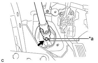
Text in Illustration *a Matchmark Put matchmarks on the No. 2 steering intermediate shaft assembly and steering intermediate shaft.
-
Remove the bolt.
-
Separate the No. 2 steering intermediate shaft assembly from the steering intermediate shaft.
-
-
REMOVE STEERING POST ASSEMBLY (for LHD)
-
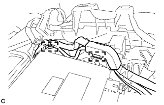
Text in Illustration *1 Lock of Lock Lever *2 Lock Lever Disconnect the connector from the power steering ECU assembly.
Tech Tips
As shown in the illustration, pull out the lock of the lock lever and turn the lock lever to disconnect the connector.
-
Disconnect the connector from the power steering ECU assembly.
-
Disengage the 2 wire harness clamps.
-
Disengage the wire harness clamps from the steering post assembly.
-
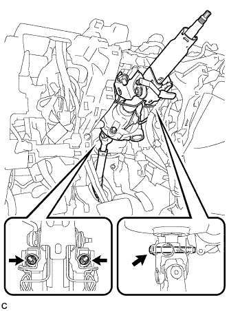
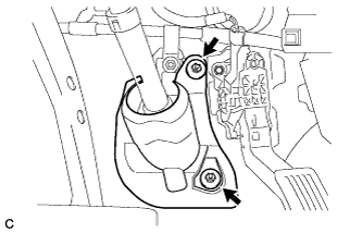
Remove the bolt, 2 nuts and steering post assembly.
-
-
REMOVE STEERING POST ASSEMBLY (for RHD)
-
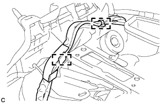
Disengage the 2 wire harness clamps.
-
Disengage the wire harness clamps from the steering post assembly.
-
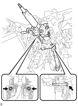
Remove the bolt, 2 nuts and steering post assembly.
-
-
REMOVE NO. 2 STEERING INTERMEDIATE SHAFT ASSEMBLY
-
Text in Illustration *a Matchmark Put matchmarks on the No. 2 steering intermediate shaft assembly and steering column assembly.
-
Remove the bolt and No. 2 steering intermediate shaft assembly from the steering column assembly.
-