REAR BRAKE REMOVAL
Note
-
When the brake pedal is first depressed after replacing the brake pads or pushing back the disc brake piston, DTC C1214 may be output. As there is no malfunction, clear the DTC.
-
While the auxiliary battery is connected, even if the power switch is off, the brake control system activates when the brake pedal is depressed or any door courtesy switch is turned on. Therefore, even if only brake pads are to be removed and installed, be sure to perform the Disable Brake Control procedure and disconnect the cable from the negative (-) terminal of the auxiliary battery before beginning work.
Tech Tips
-
Use the same procedure for the LH side and RH side.
-
The following procedure is for the LH side.
-
PRECAUTION
Note
After turning the power switch off, waiting time may be required before disconnecting the cable from the negative (-) auxiliary battery terminal. Therefore, make sure to read the disconnecting the cable from the negative (-) auxiliary battery terminal notices before proceeding with work Click here.
-
DISABLE BRAKE CONTROL
-
Wait at least 2 minutes after the power switch off.
Note
When the brake pedal is depressed or the door courtesy switch is turned on even if the power switch is off, the brake control system activates. Therefore do not depress the brake pedal or open/close the doors until the reservoir level switch connector is disconnected.
-
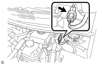
Disconnect the reservoir level switch connector with the parking brake applied.
-
Disconnect the cable from the negative (-) auxiliary battery terminal.
-
for 2ZR-FXE: Click here
-
for 5ZR-FXE: Click here
-
-
Depress the brake pedal 40 times or more to return all the fluid in the accumulator back to the reservoir.
-
Check that the brake pedal cannot be further depressed.
-
Release the parking brake.
-
-
REMOVE REAR WHEEL
-
DRAIN BRAKE FLUID
Note
If brake fluid leaks onto any painted surface, immediately wash it off.
-
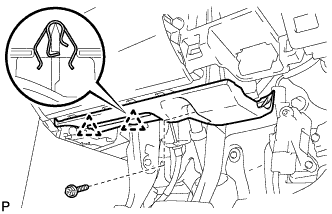
REMOVE NO. 1 INSTRUMENT PANEL UNDER COVER SUB-ASSEMBLY (for LHD)
-
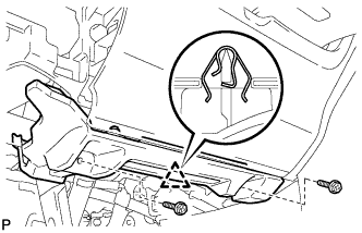
Remove the 2 screws <E>.
-
Disengage the clip.
-
Disengage the clamp.
-
Disconnect each connector and remove the No. 1 instrument panel under cover sub-assembly.
-
-
DISCONNECT FRONT DOOR OPENING TRIM WEATHERSTRIP LH (for LHD)
-
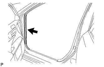
Disconnect the front door opening trim weatherstrip.
-
Remove the residual weatherstrip sealant from the body of the vehicle using cleaner.
Note
Remove the sealant completely. Any residual sealant may transfer to other areas of the vehicle when removing/installing the interior parts.
-
-
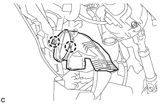
REMOVE INSTRUMENT SIDE PANEL LH (for LHD)
-
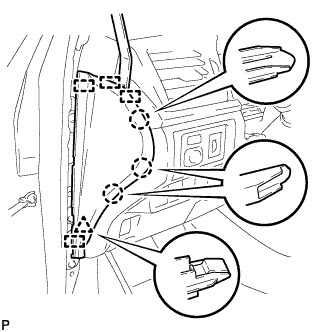
Using a moulding remover, disengage the 3 claws, clip and 4 guides, and remove the instrument side panel LH.
-
-
REMOVE LOWER INSTRUMENT PANEL FINISH PANEL SUB-ASSEMBLY (for LHD)
-
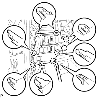
Using a moulding remover, disengage the 8 claws and clip.
-
Disconnect each connector and remove the lower instrument panel finish panel sub-assembly.
-
-
LOOSEN PARKING BRAKE CABLE (for LHD)
-
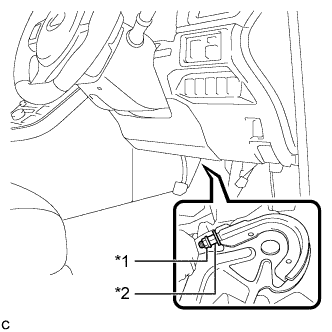
Completely release the parking brake pedal.
-
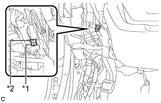
Text in Illustration *1 Lock Nut *2 Adjusting Nut Loosen the lock nut and adjusting nut to completely release the parking brake cable.
-
-
REMOVE NO. 1 INSTRUMENT PANEL UNDER COVER SUB-ASSEMBLY (for RHD)
-
Remove the screw <E>.
-
Disengage the 2 clips.
-
Disengage the clamp.
-
Disconnect each connector and remove the No. 1 instrument panel under cover sub-assembly.
-
-
REMOVE NO. 2 AIR DUCT SUB-ASSEMBLY (for RHD)
-
Disengage the 2 claws to remove the No. 2 air duct sub-assembly.
-
-
LOOSEN PARKING BRAKE CABLE (for RHD)
-
Completely release the parking brake pedal.
-
Text in Illustration *1 Lock Nut *2 Adjusting Nut Loosen the lock nut and the adjusting nut to completely release the parking brake cable.
-
-
REMOVE PARKING BRAKE LEVER PROTECTOR
-
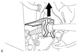
Remove the parking brake lever protector from the No. 3 parking brake cable assembly.
-
-
DISCONNECT NO. 3 PARKING BRAKE CABLE ASSEMBLY
-

Remove the bolt and separate the No. 3 parking brake cable assembly.
-
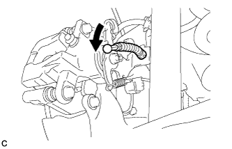
Separate the No. 3 parking brake cable assembly from the rear disc brake cylinder assembly.
-
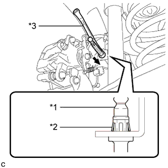
Text in Illustration *1 No. 3 Parking Brake Cable Assembly *2 Clip *3 Offset Wrench (14 mm) Separate the No. 3 parking brake cable assembly from the rear disc brake cylinder assembly.
Tech Tips
Insert an offset wrench (14 mm) at the base of the No. 3 parking brake cable assembly as shown in the illustration to disengage the clip. Pull out the No. 3 parking brake cable assembly from the rear disc brake cylinder assembly.
-
-
SEPARATE REAR FLEXIBLE HOSE
-
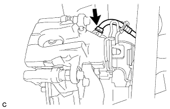
Remove the union bolt and gasket, and separate the rear flexible hose from the rear disc brake cylinder assembly.
-
-
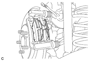
REMOVE REAR DISC BRAKE CYLINDER ASSEMBLY
-
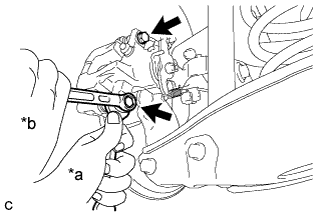
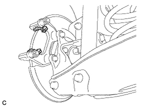
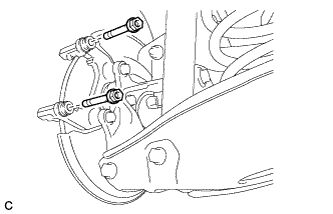
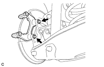
Text in Illustration *a Hold *b Turn Hold the rear disc brake pad guide pin, and remove the 2 bolts and rear disc brake cylinder assembly.
Note
Remove the rear disc brake cylinder assembly while holding both of the rear disc brake pads because the anti-squeal springs may fall off the rear disc brake pads.
-
-
REMOVE REAR DISC BRAKE PAD
-
Remove the 2 anti-squeal springs from the rear disc brake pads.
-
Remove the 2 rear disc brake pads from the disc brake cylinder mounting.
-
-
REMOVE REAR DISC BRAKE ANTI-SQUEAL SHIM
-
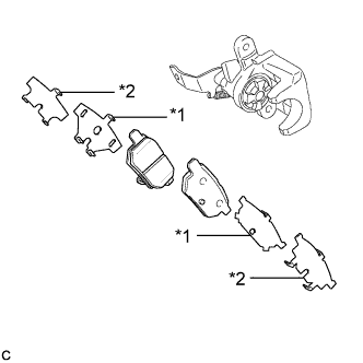
Text in Illustration *1 Rear No. 1 Disc Brake Anti-squeal Shim *2 Rear No. 2 Disc Brake Anti-squeal Shim Remove the rear No. 1 disc brake anti-squeal shim and rear No. 2 disc brake anti-squeal shim from each rear disc brake pad.
-
-
REMOVE REAR DISC BRAKE PAD SUPPORT PLATE
-
Remove the 2 rear disc brake pad support plates from the disc brake cylinder mounting.
Note
Each rear disc brake pad support plate has a different shape. Be sure to put an identification mark on each rear disc brake pad support plate so that it can be reinstalled to its original position.
-
-
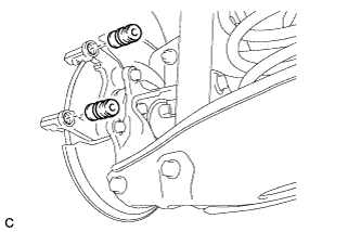
REMOVE REAR DISC BRAKE PAD GUIDE PIN
-
Remove the 2 rear disc brake pad guide pins from the disc brake cylinder mounting.
-
-
REMOVE REAR DISC BRAKE BUSHING DUST BOOT
-
Remove the 2 rear disc brake bushing dust boots from the disc brake cylinder mounting.
-
-
REMOVE DISC BRAKE CYLINDER MOUNTING
-
Remove the 2 bolts and disc brake cylinder mounting.
-
-
REMOVE REAR DISC
-
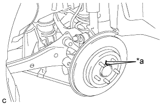
Text in Illustration *a Matchmark Put matchmarks on the disc and the axle hub.
-
Remove the rear disc.
-