-
Do not drop the brake pedal stroke sensor assembly.
-
If the brake pedal stroke sensor assembly has been dropped, replace the brake pedal stroke sensor assembly with a new one.
- Click here
INSPECT AND ADJUST BRAKE PEDAL HEIGHT
-
Check the brake pedal height.
-
Turn back the carpet.
-
Turn back the dash silencer from the slit provided on the dash silencer.
-
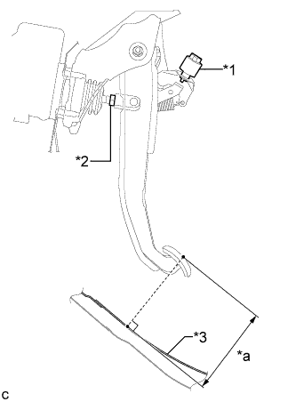
Measure the shortest distance between the brake pedal surface and floor panel.
Table 1. Text in Illustration *1 Stop Light Switch Assembly *2 Clevis Lock Nut *3 Floor Panel *a Brake Pedal Height Brake pedal height from floor panel Brake Pedal Specified Value w/o Aluminum Pedal 131.3 to 141.3 mm (5.17 to 5.56 in.) w/ Aluminum Pedal 133.3 to 143.3 mm (5.25 to 5.64 in.)
-
-
Adjust the brake pedal height.
-
Remove the stop light switch assembly (Click here).
-
Loosen the clevis lock nut.
-
Adjust the brake pedal height by turning the push rod.
-
Tighten the clevis lock nut.
26 N*m 260 kgf*cm 19 ft.*lbf -
Install and adjust the stop light switch assembly (Click here).
-
-
- Click here
INSTALL BRAKE PEDAL STROKE SENSOR ASSEMBLY
Note:
-
Do not drop the brake pedal stroke sensor assembly.
-
If the brake pedal stroke sensor assembly has been dropped, replace the brake pedal stroke sensor with a new one.
-
When installing a new brake pedal stroke sensor assembly:
Note:Do not break the brake pedal stroke sensor assembly lever set pin before installing the brake pedal stroke sensor assembly with the nut.
-
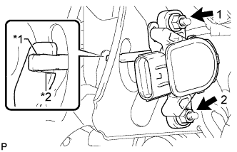
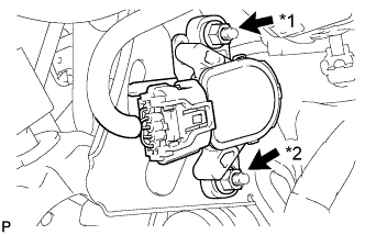
Install a new brake pedal stroke sensor assembly with the 2 nuts.
Table 2. Text in Illustration *1 Brake Pedal Stroke Sensor Assembly Lever *2 Brake Pedal Groove 7.0 N*m 71 kgf*cm 62 in.*lbf Note:
-
Engage the brake pedal stroke sensor assembly lever with the brake pedal groove.
-
Check that there is no foreign matter attached to the contact surface of the brake pedal stroke sensor assembly.
-
Check that the tip of the brake pedal stroke sensor assembly lever is protruding from the brake pedal groove.
-
Tighten the 2 nuts in the order shown in the illustration.
-
-
Connect the connector.
-
Firmly depress the brake pedal and break the brake pedal stroke sensor assembly lever set pin.
-
Remove the broken lever set pin.
-
-
When reusing the brake pedal stroke sensor assembly:
-
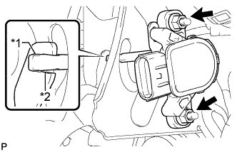
Temporarily install the brake pedal stroke sensor assembly with the 2 nuts.
Table 3. Text in Illustration *1 Brake Pedal Stroke Sensor Assembly Lever *2 Brake Pedal Groove Note:
-
Engage the brake pedal stroke sensor assembly lever with the brake pedal groove.
-
Check that there is no foreign matter attached to the contact surface of the brake pedal stroke sensor assembly.
-
Check that the tip of the brake pedal stroke sensor assembly lever is protruding from the brake pedal groove.
-
-
Connect the connector.
-
-
- Click here
ADJUST BRAKE PEDAL STROKE SENSOR ASSEMBLY
Note:When the brake pedal stroke sensor assembly is being reused, perform the following procedure to adjust it.
-
Connect the cable to the negative (-) auxiliary battery terminal.
-
Connect the intelligent tester to the DLC3.
-
Turn the power switch on (IG).
-
Turn the intelligent tester on.
-
Enter the following menus: Chassis / ABS/VSC/TRC / Data List "Stroke Sensor".
-
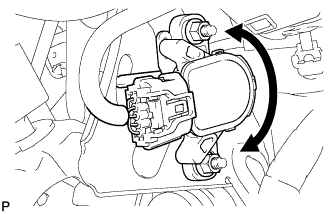
Read the stroke sensor value in the Data List, and turn the brake pedal stroke sensor assembly slowly to the right or left to adjust the output voltage so that it is within the following range.
Standard voltage (without the brake pedal depressed) 0.8 to 1.2 V -
Tighten the 2 nuts.
7.0 N*m 71 kgf*cm 62 in.*lbf Note:
-
Do not depress the brake pedal after turning the power switch on (IG).
-
Tighten the 2 nuts in the order shown in the illustration.
-
-
Turn the power switch off.
-
Disconnect the intelligent tester.
-
Disconnect the cable from the negative (-) auxiliary battery terminal.
-
- Click here
INSTALL LOWER NO. 1 INSTRUMENT PANEL AIRBAG ASSEMBLY
- Click here
CHECK AND CLEAR DTC
- Click here
PERFORM INITIALIZATION AND CALIBRATION OF LINEAR SOLENOID VALVE