| DTC Code | DTC Name |
|---|---|
| U0073/94 | Control Module Communication Bus OFF |
| U0123/62 | Lost Communication with Yaw Rate Sensor Module |
| U0124/95 | Lost Communication with Lateral Acceleration Sensor Module |
| U0126/63 | Lost Communication with Steering Angle Sensor Module |
| U0293/59 | Communication Error from HV ECU |
DESCRIPTION
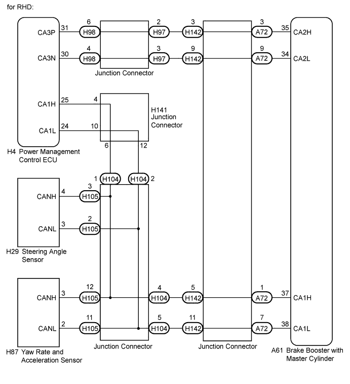
The skid control ECU receives the signals from the power management control ECU, steering angle sensor, and yaw rate and acceleration sensor via the CAN communication system.
| DTC Code | INF Code | DTC Detection Condition | Trouble Area |
|---|---|---|---|
| U0073/94 | 461 | Either of the following is detected:
|
|
| ↑ | 462 | Either of the following is detected:
|
|
| ↑ | 463 464 |
Bus off occurs once or more per 0.1 seconds 10 times repeatedly. |
|
| ↑ | 465 466 |
Sending does not complete within 5 seconds after data is output from the skid control ECU. | ↑ |
| U0123/62 | 731 | Yaw rate sensor communication is disabled for 1 second or more. |
|
| ↑ | 732 | Yaw rate sensor communication is disabled once or more per 5 seconds 10 times or more within 60 seconds. | ↑ |
| U0124/95 | 591 | Acceleration sensor communication is disabled for 1 second or more. |
|
| ↑ | 592 | Acceleration sensor communication is disabled once per 5 seconds 10 times or more within 60 seconds. | ↑ |
| U0126/63 | 741 | Steering angle sensor communication is disabled for 1 second or more. |
|
| ↑ | 742 | Steering angle sensor communication is disabled once or more per 5 seconds 10 times or more within 60 seconds. | ↑ |
| U0293/59 | 411 412 413 |
Either of the following is detected:
|
|
INSPECTION PROCEDURE
PROCEDURE
- Click here
CHECK HARNESS AND CONNECTOR (MOMENTARY INTERRUPTION)
-
Using the intelligent tester, check for any momentary interruptions in the wire harness and connector corresponding to a DTC (Click here).
Table 1. ABS/VSC/TRC Tester Display Measurement Item/Range Normal Condition Diagnostic Note Yaw Rate Open Yaw rate sensor open detection / Error or Normal Error: Momentary interruption
Normal: Normal
- Steering Open Steering angle sensor open detection / Error or Normal Error: Momentary interruption
Normal: Normal
- HV Communication Open Hybrid vehicle communication open detection / Error or Normal Error: Momentary interruption
Normal: Normal
- Result Result Proceed to There is a constant open circuit A There are no momentary interruptions B There are momentary interruptions C Tip:Perform the above inspection before removing any sensor or connector.
-
- Click here
CHECK IF EACH SENSOR AND ECU CONNECTOR ARE SECURELY CONNECTED
-
Turn the power switch off.
-
Check if each sensor and ECU connector are securely connected.
OK Each sensor and ECU connector are securely connected.
- OKClick here
- NGClick here
-
- Click here
RECONFIRM DTC
-
Turn the power switch off.
-
Record the output DTCs (for ABS, VSC, electronically controlled brake system, and/or CAN communication system) (Click herefor ABS, VSC and/or electronically controlled brake system, orClick herefor CAN communication system).
Tip:If the CAN communication system DTC and the relevant sensor DTCs are output simultaneously, troubleshoot the relevant sensor DTCs (for ABS, VSC and/or electronically controlled brake system) after the CAN communication system returns to normal.
Result Result Proceed to DTC is not output A DTC (ABS, VSC and/or electronically controlled brake system DTC) is output B DTC (CAN communication system DTC) is output C
-
- Click here
REPAIR OR REPLACE HARNESS OR CONNECTOR
-
Turn the power switch off.
-
Repair or replace the harness or connector.
-
Check for any momentary interruption between the skid control ECU and each sensor or ECU (Click here).
-
Check that there are no momentary interruptions.
- NEXTClick here
-
- Click here
RECONFIRM DTC
-
Turn the power switch off.
-
Clear the DTCs (Click here).
-
Turn the power switch on (READY).
-
Drive the vehicle and turn the steering wheel to the right and left at a speed of 15 km/h (9 mph) or more.
-
Check that no CAN communication system DTC is output (Click here).
-
If ABS, VSC and/or electronically controlled brake system DTCs are output, record them (Click here).
Result Result Proceed to DTC is not output A DTC (ABS, VSC and/or electronically controlled brake system DTC) is output B DTC (CAN communication system DTC) is output C Tip:The CAN communication system must be normal when repairing each sensor DTC (for ABS, VSC and/or electronically controlled brake system).
-
- Click here
CHECK FOR INTERMITTENT PROBLEMSClick here
- Click here
END
- Click here
CONNECT CONNECTOR TO EACH SENSOR OR ECU CORRECTLY
- Click here
REPAIR CIRCUITS INDICATED BY OUTPUT DTCSClick here
- Click here
INSPECT CAN COMMUNICATION SYSTEMClick here