FRONT STABILIZER BAR INSTALLATION
-
INSTALL FRONT STABILIZER BAR BUSHING LH
-
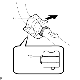
Text in Illustration *1 Stopper *2 Dust Lip 
Front of the Vehicle 
Inside of the Vehicle Install the front stabilizer bar bushing to the outside of the stopper on the front stabilizer bar as shown in the illustration.
Note
-
Install the front stabilizer bar bushing so that the dust lips face outward.
-
Install the front stabilizer bar bushing so that the cutouts face rearward.
-
-
-
INSTALL FRONT STABILIZER BAR BUSHING RH
Tech Tips
Perform the same procedure as for the LH side.
-
INSTALL FRONT STABILIZER BAR
-
Install the front stabilizer bar to the front suspension crossmember sub-assembly so that the identification marks are positioned on the right side of the vehicle.
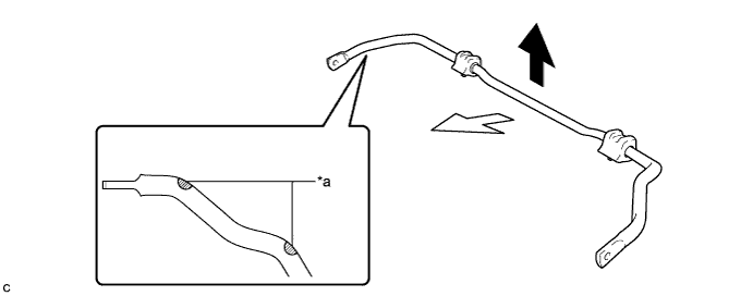
Text in Illustration *a Identification Mark - - Top of the Vehicle Front of the Vehicle
-
-
INSTALL FRONT SUSPENSION MEMBER BRACE
-
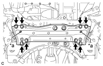
Text in Illustration *a Protrusion Install the front suspension member brace with the 8 bolts.
- Torque:
- 92 N*m { 938 kgf*cm, 68 ft.*lbf }
Note
-
After installing the front suspension member brace, make sure that the protrusions of the front stabilizer bar bushings are visible.
-
-
TEMPORARILY INSTALL FRONT LOWER NO. 1 SUSPENSION ARM SUB-ASSEMBLY LH
-
Temporarily install the front lower No. 1 suspension arm sub-assembly LH to the front suspension crossmember sub-assembly with the 2 bolts and nut.
Note
Because the nut has its own stopper, do not turn the nut.
-
-
CONNECT FRONT LOWER NO. 1 SUSPENSION ARM SUB-ASSEMBLY LH
-
Install the front lower No. 1 suspension arm sub-assembly to the front lower ball joint assembly with the bolt and 2 nuts.
- Torque:
- 89 N*m { 908 kgf*cm, 66 ft.*lbf }
-
-
INSTALL FRONT STABILIZER LINK ASSEMBLY LH
-
Install the front stabilizer link assembly LH with the 2 nuts.
- Torque:
- 74 N*m { 755 kgf*cm, 55 ft.*lbf }
Tech Tips
If the ball joint turns together with the nut, use a hexagon wrench (6 mm) to hold the stud bolt.
-
-
INSTALL FRONT STABILIZER LINK ASSEMBLY RH
Tech Tips
Perform the same procedure as for the LH side.
-
INSTALL FRONT WHEELS
- Torque:
- 103 N*m { 1050 kgf*cm, 76 ft.*lbf }
-
STABILIZE SUSPENSION
-
Lower the vehicle.
-
Press down on the vehicle several times to stabilize the suspension.
-
-
FULLY TIGHTEN FRONT LOWER NO. 1 SUSPENSION ARM SUB-ASSEMBLY LH
-
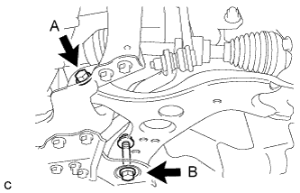
Fully tighten the bolt A and B.
- Torque:
- Bolt A
- 233 N*m { 2376 kgf*cm, 172 ft.*lbf }
- Bolt B
- 214 N*m { 2182 kgf*cm, 158 ft.*lbf }
Note
Because the nut has its own stopper, do not turn the nut.
-
-
INSTALL NO. 1 ENGINE UNDER COVER
-
INSPECT AND ADJUST FRONT WHEEL ALIGNMENT