REAR LOWER ARM INSTALLATION
Tech Tips
-
Use the same procedure for the RH side and LH side.
-
The procedure listed below is for the LH side.
-
TEMPORARILY TIGHTEN REAR NO. 2 SUSPENSION ARM ASSEMBLY
-
Temporarily install the rear No. 2 suspension arm assembly to the rear suspension member sub-assembly with the bolt and nut.
Note
-
Since a stopper nut is used, turn the bolt.
-
Insert the bolt with the threaded end facing the front of the vehicle.
-
-
-
INSTALL REAR UPPER COIL SPRING INSULATOR
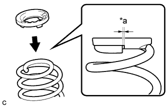
Text in Illustration *a 10 mm or less
-
Install the rear upper coil spring insulator to the rear coil spring.
Note
Install the rear upper coil spring insulator so that the dimension between the stopper and upper end of the rear coil spring is 10 mm (0.394 in.) or less.
-
-
INSTALL REAR LOWER COIL SPRING INSULATOR
-
Install the rear lower coil spring insulator to the rear No. 2 suspension arm assembly.
-
-
INSTALL REAR COIL SPRING
-
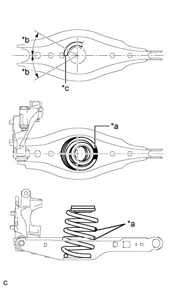
Text in Illustration *a Identification Mark *b 30° or less *c Lower End of Rear Coil Spring Set the rear coil spring to the rear No. 2 suspension arm assembly.
Note
-
Set the rear coil spring so that the identification marks are positioned as shown in the illustration.
-
Set the rear coil spring so that its lower end is within the range shown in the illustration.
-
-
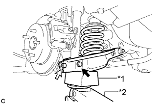
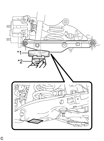
Text in Illustration *1 Wooden Block *2 Jack 
Bolt (A) 
Bolt (B) Using a jack and wooden block, slowly jack up the rear No. 2 suspension arm assembly.
CAUTION:
Do not jack up the rear No. 2 suspension arm assembly too high as the vehicle may fall.
Note
-
When jacking up the rear No. 2 suspension arm assembly, be sure to jack it up slowly.
-
Make sure to perform this operation with the vehicle kept as low as possible.
-
-
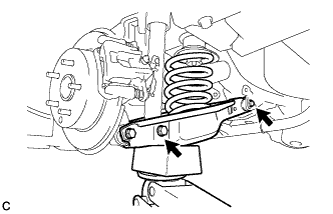
Temporarily install the rear No. 2 suspension arm assembly and rear coil spring with the bolt (A) and nut.
Note
-
Since a stopper nut is used, turn the bolt.
-
Insert the bolt with the threaded end facing the front of the vehicle.
-
-
Install the rear No. 2 suspension arm assembly to the rear axle assembly with the bolt (B) and nut.
- Torque:
- 90 N*m { 918 kgf*cm, 66 ft.*lbf }
Note
-
Since a stopper nut is used, turn the bolt.
-
Insert the bolt with the threaded end facing the front of the vehicle.
-
-
INSTALL REAR STABILIZER LINK ASSEMBLY
Note
Since the rear stabilizer link assembly LH, rear stabilizer cushions and nut (B) are not reusable, new parts must be installed.
-
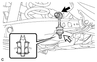
Install a new rear stabilizer link assembly LH and 2 new rear stabilizer cushions to the rear No. 2 suspension arm assembly with a new nut (B) as shown in the illustration.
Text in Illustration Nut (A) Nut (B) - Torque:
- 30 N*m { 306 kgf*cm, 22 ft.*lbf }
Note
Be sure to install the rear stabilizer cushions in the correct direction as shown in the illustration.
-
Install the rear stabilizer link assembly LH to the rear stabilizer bar with the nut (A).
- Torque:
- 95 N*m { 969 kgf*cm, 70 ft.*lbf }
Tech Tips
If the ball joint turns together with the nut, use a hexagon socket wrench to hold the stud bolt.
-
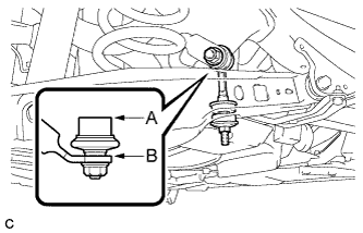
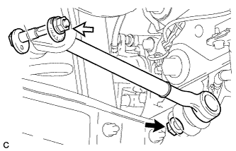
Adjust the rear stabilizer link assembly LH so that A and B are parallel as shown in the illustration.
-
-
INSTALL REAR HEIGHT CONTROL SENSOR SUB-ASSEMBLY (w/ Height Control Sensor)
-
Engage the 2 guides and install the rear height control sensor sub-assembly with the 2 bolts.
- Torque:
- 8.0 N*m { 82 kgf*cm, 71 in.*lbf }
-
Connect the connector.
-
Engage the clamp.
-
-
INSTALL REAR SUSPENSION MEMBER BRACE
-
Install the rear suspension member brace LH to the rear suspension member sub-assembly with the 3 bolts.
- Torque:
- 35 N*m { 357 kgf*cm, 26 ft.*lbf }
-
-
TEMPORARILY TIGHTEN REAR NO. 1 SUSPENSION ARM ASSEMBLY
-
Temporarily tighten the rear No. 1 suspension arm assembly to the rear axle assembly with a new nut (A).
Text in Illustration Nut (A) Nut (B) -
Using the rear suspension toe adjust cam sub-assembly, No. 2 camber adjust cam and nut (B), temporarily install the rear No. 1 suspension arm assembly to the rear suspension member sub-assembly.
Note
-
Insert the rear suspension toe adjust cam sub-assembly from the rear of the vehicle.
-
Hold the rear suspension toe adjust cam sub-assembly while rotating the nut.
-
-
Fully tighten the nut (A).
- Torque:
- 100 N*m { 1020 kgf*cm, 74 ft.*lbf }
-
-
STABILIZE SUSPENSION
-
Text in Illustration *1 Wooden Block *2 Jack 
Wooden Block placement location Using a jack and wooden block as shown in the illustration, jack up the rear No. 2 suspension arm assembly to keep it level so that the suspension is positioned at the vehicle standard height position (position for final tightening of the suspension).
CAUTION:
Do not jack up the rear No. 2 suspension arm assembly too high as the vehicle may fall.
Note
-
When jacking up the rear No. 2 suspension arm assembly, be sure to jack it up slowly.
-
Make sure to perform this operation with the vehicle kept as low as possible.
Tech Tips
-
If the rear No. 2 suspension arm assembly cannot be positioned within the specification even when the rear No. 2 suspension arm assembly is jacked up, apply additional load such as by placing a weight in the luggage compartment.
-
This procedure duplicates standard vehicle height conditions.
-
Use the same procedure for the RH side and LH side.
-
-
-
FULLY TIGHTEN REAR NO. 2 SUSPENSION ARM ASSEMBLY
-
Fully tighten the 2 bolts.
- Torque:
- 90 N*m { 918 kgf*cm, 66 ft.*lbf }
Note
-
Since a stopper nut is used, turn the bolts.
-
Make sure that the rear No. 2 suspension arm assembly remains level when fully tightening the bolt.
-
-
INSTALL REAR FLOOR SIDE MEMBER COVER (w/ Floor Under Cover)
-
for LH Side:
-
Install the rear floor side member cover LH with the 2 bolts, nut and 2 clips.
-
-
for RH Side:
-
Install the rear floor side member cover RH with the bolt, nut and 2 clips.
-
-
-
INSTALL REAR SUSPENSION ARM COVER
-
Insert the 2 claws of the rear suspension arm cover into the rear No. 2 suspension arm assembly.
-
Install the rear suspension arm cover with the 2 bolts.
- Torque:
- 12 N*m { 122 kgf*cm, 9 ft.*lbf }
Note
Make sure that the 2 claws of the rear suspension arm cover are inserted.
-
-
INSTALL REAR WHEEL
- Torque:
- 103 N*m { 1050 kgf*cm, 76 ft.*lbf }
-
FULLY TIGHTEN REAR NO. 1 SUSPENSION ARM ASSEMBLY
-
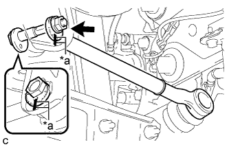
Text in Illustration *a Matchmarks Align the matchmarks on the No. 2 camber adjust cam, rear suspension toe adjust cam sub-assembly and rear suspension member sub-assembly.
-
Fully tighten the nut to install the rear No. 1 suspension arm assembly.
- Torque:
- 100 N*m { 1020 kgf*cm, 74 ft.*lbf }
Note
-
Hold the rear suspension toe adjust cam sub-assembly while rotating the nut.
-
Make sure that the vehicle is unloaded when fully tightening the nut.
-
-
INSPECT AND ADJUST REAR WHEEL ALIGNMENT
-
HEIGHT CONTROL SENSOR SIGNAL INITIALIZATION (w/ Height Control Sensor)
-
INSPECT AND ADJUST HEADLIGHT AIMING (w/ Height Control Sensor)