REAR LOWER ARM REMOVAL

Tech Tips
-
Use the same procedure for the RH side and LH side.
-
The procedure listed below is for the LH side.
-
REMOVE REAR WHEEL
-
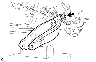
REMOVE REAR SUSPENSION ARM COVER
-
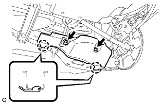
Remove the 2 bolts and disengage the 2 claws to remove the rear suspension arm cover from the rear No. 2 suspension arm assembly.
-
-
REMOVE REAR FLOOR SIDE MEMBER COVER (w/ Floor Under Cover)
-
for LH Side:
-
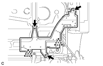
Remove the 2 bolts, nut and clip.
-
Disengage the clip and remove the rear floor side member cover LH.
-
-
for RH Side:
-
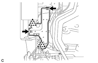
Remove the bolt and nut.
-
Disengage the 2 clips and remove the rear floor side member cover RH.
-
-
-
REMOVE REAR NO. 1 SUSPENSION ARM ASSEMBLY
-
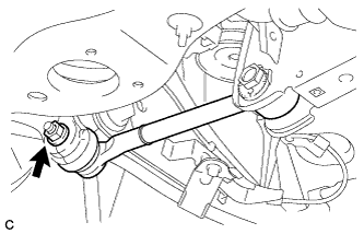
Remove the nut.
-
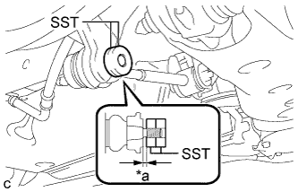
Text in Illustration *a 1 mm or more Install 2 spacers (SST spacer B) as shown in the illustration.
- SST
- 09960-20010 ( 09961-02060 )
Note
As SST may be damaged, make sure that the clearance between the rear axle assembly and spacers is 1 mm (0.0394 in.) or more.
-
Using SST, separate the rear No. 1 suspension arm assembly from the rear axle assembly as shown in the illustration.
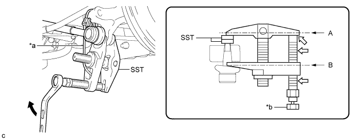
Text in Illustration *a Tie the string without any slack. *b Place a wrench here. 
Turn 
Grease - SST
- 09960-20010 ( 09961-02010, 09961-02060 )
CAUTION:
Apply grease to the threads and end of the SST bolt.
Note
-
Be sure to tighten the string firmly to secure SST to the rear axle assembly to prevent SST from falling off.
-
Install SST so that A and B are parallel.
-
Be sure to place a wrench on the part indicated in the illustration.
-
Do not damage the ball joint dust cover.
-
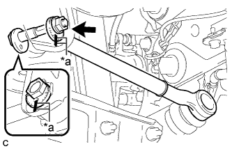
Text in Illustration *a Matchmarks Place matchmarks on the No. 2 camber adjust cam, rear suspension toe adjust cam sub-assembly and rear suspension member sub-assembly.
-
Remove the nut, No. 2 camber adjust cam, rear suspension toe adjust cam sub-assembly and rear No. 1 suspension arm assembly.
Note
Hold the rear suspension toe adjust cam sub-assembly while rotating the nut.
-
-
REMOVE REAR HEIGHT CONTROL SENSOR SUB-ASSEMBLY (w/ Height Control Sensor)
-
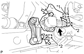
Text in Illustration *1 Clamp *2 Guide Disengage the clamp.
-
Disconnect the connector.
-
Remove the 2 bolts.
-
Disengage the 2 guides and remove the rear height control sensor sub-assembly.
Note
Do not drop the rear height control sensor sub-assembly. If it is dropped, replace it with a new one.
-
-
REMOVE REAR STABILIZER LINK ASSEMBLY
-
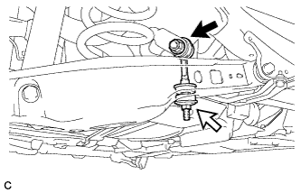
Remove the nut (A) and separate the rear stabilizer link assembly LH from the rear stabilizer bar.
Text in Illustration Nut (A) Nut (B) Tech Tips
If the ball joint turns together with the nut, use a hexagon socket wrench to hold the stud bolt.
-
Remove the nut (B), rear stabilizer link assembly LH and 2 rear stabilizer cushions.
-
-
REMOVE REAR SUSPENSION MEMBER BRACE
-
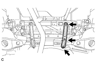
Remove the 3 bolts and rear suspension member brace LH from the rear suspension member sub-assembly.
-
-
REMOVE REAR COIL SPRING
-
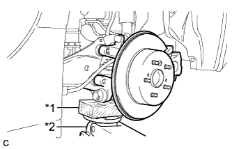
Text in Illustration *1 Wooden Block *2 Jack Support the rear axle assembly with a jack using a wooden block as shown in the illustration.
Note
Keep supporting the rear axle assembly with a jack until the installation of the rear coil spring has been completed.
-
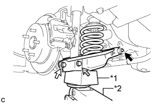
Text in Illustration *1 Wooden Block *2 Jack Bolt (A) Bolt (B) 
Bolt (C) Support the rear No. 2 suspension arm assembly using a jack and wooden block.
Note
-
When jacking up the rear No. 2 suspension arm assembly, be sure to jack it up slowly.
-
Make sure to perform this operation with the vehicle kept as low as possible.
-
-
Loosen the bolt (A).
Note
-
Since a stopper nut is used, turn the bolt.
-
Do not remove the bolt.
-
-
Remove the bolt (B) and nut, and separate the rear No. 2 suspension arm assembly from the rear axle assembly.
Note
Since a stopper nut is used, turn the bolt.
-
Remove the bolt (C) and nut, and then slowly lower the rear No. 2 suspension arm assembly, and remove the rear coil spring.
Note
Since a stopper nut is used, turn the bolt.
-
-
REMOVE REAR UPPER COIL SPRING INSULATOR
-
Remove the rear upper coil spring insulator.
-
-
REMOVE REAR LOWER COIL SPRING INSULATOR
-
Remove the rear lower coil spring insulator.
-
-
REMOVE REAR NO. 2 SUSPENSION ARM ASSEMBLY
-
Remove the bolt, nut and rear No. 2 suspension arm assembly from the rear suspension member sub-assembly.
Note
Since a stopper nut is used, turn the bolt.
-