REAR UPPER ARM INSTALLATION
Tech Tips
-
Use the same procedure for the RH side and LH side.
-
The procedure listed below is for the LH side.
-
TEMPORARILY TIGHTEN REAR UPPER CONTROL ARM ASSEMBLY
-
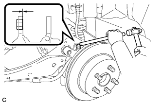
Using a brass bar and a hammer, push out the bushing until it is positioned as shown in the illustration.
Tech Tips
Pushing out the bushing makes it easier to install the rear upper control arm assembly.
-
Use a jack and wooden block to keep the rear No. 2 suspension arm assembly level.
CAUTION:
Do not jack up the rear No. 2 suspension arm assembly too high as the vehicle may fall.
Note
-
When jacking up the rear No. 2 suspension arm assembly, be sure to jack it up slowly.
-
Make sure to perform this operation with the vehicle kept as low as possible.
-
-
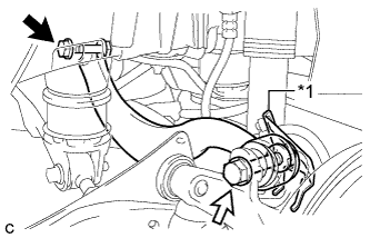
Text in Illustration *1 No. 2 Flexible Hose Bracket 
Bolt (A) 
Bolt (B) Temporarily tighten the rear upper control arm assembly to the rear suspension member sub-assembly with the bolt (A) and nut.
Note
-
Since a stopper nut is used, turn the bolt.
-
Insert the bolt with the threaded end facing the rear of the vehicle.
-
-
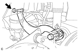
Fully tighten the rear upper control arm assembly and No. 2 flexible hose bracket to the rear axle assembly with the bolt (B) and nut.
- Torque:
- 90 N*m { 918 kgf*cm, 66 ft.*lbf }
Note
-
Since a stopper nut is used, turn the bolt.
-
Insert the bolt with the threaded end facing the rear of the vehicle.
-
-
STABILIZE SUSPENSION
-
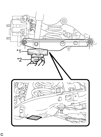
Text in Illustration *1 Wooden Block *2 Jack 
Wooden Block placement location Using a jack and wooden block as shown in the illustration, jack up the rear No. 2 suspension arm assembly to keep it level so that the suspension is positioned at the vehicle standard height position (position for final tightening of the suspension).
CAUTION:
Do not jack up the rear No. 2 suspension arm assembly too high as the vehicle may fall.
Note
-
When jacking up the rear No. 2 suspension arm assembly, be sure to jack it up slowly.
-
Make sure to perform this operation with the vehicle kept as low as possible.
Tech Tips
-
If the rear No. 2 suspension arm assembly cannot be positioned within the specification even when the rear No. 2 suspension arm assembly is jacked up, apply additional load such as by placing a weight in the luggage compartment.
-
This procedure duplicates standard vehicle height conditions.
-
Use the same procedure for the RH side and LH side.
-
-
-
FULLY TIGHTEN REAR UPPER CONTROL ARM ASSEMBLY
-
Fully tighten the bolt.
- Torque:
- 90 N*m { 918 kgf*cm, 66 ft.*lbf }
Note
-
Since a stopper nut is used, turn the bolt.
-
Make sure that the rear No. 2 suspension arm assembly remains level when fully tightening the bolt.
-
-
INSTALL REAR FLOOR SIDE MEMBER COVER (w/ Floor Under Cover)
-
for LH Side:
-
Install the rear floor side member cover LH with the 2 bolts, nut and 2 clips.
-
-
for RH Side:
-
Install the rear floor side member cover RH with the bolt, nut and 2 clips.
-
-
-
INSTALL REAR SUSPENSION ARM COVER
-
Insert the 2 claws of the rear suspension arm cover into the rear No. 2 suspension arm assembly.
-
Install the rear suspension arm cover with the 2 bolts.
- Torque:
- 12 N*m { 122 kgf*cm, 9 ft.*lbf }
Note
Make sure that the 2 claws of the rear suspension arm cover are inserted.
-
-
INSTALL REAR WHEEL
- Torque:
- 103 N*m { 1050 kgf*cm, 76 ft.*lbf }
-
INSPECT AND ADJUST REAR WHEEL ALIGNMENT