TCM REMOVAL
-
PRECAUTION
CAUTION:
Be sure to read Precaution thoroughly before servicing Click here.
Note
After turning the power switch off, waiting time may be required before disconnecting the cable from the negative (-) auxiliary battery terminal. Therefore, make sure to read the disconnecting the cable from the negative (-) auxiliary battery terminal notices before proceeding with work Click here.
-
REMOVE REAR NO. 2 FLOOR BOARD
-
Remove the rear No. 2 floor board.
-
-
REMOVE REAR DECK FLOOR BOX
-
Remove the rear deck floor box.
-
-
REMOVE REAR NO. 3 FLOOR BOARD
-
Remove the rear No. 3 floor board.
-
-
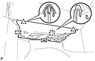
REMOVE DECK FLOOR BOX RH
-
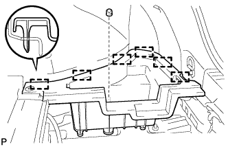
Remove the clip.
-
Disengage the 6 guides and remove the deck floor box RH.
-
-
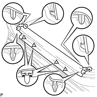
REMOVE REAR FLOOR BOARD UPPER NO. 3 PLATE
-
Disengage the 4 claws and 2 guides, and remove the rear floor board upper No. 3 plate.
-
-
DISCONNECT CABLE FROM NEGATIVE AUXILIARY BATTERY TERMINAL
CAUTION:
Wait at least 90 seconds after disconnecting the cable from the negative (-) battery terminal to disable the SRS system.
Note
When disconnecting the cable, some systems need to be initialized after the cable is reconnected Click here.
-
REMOVE FRONT DOOR SCUFF PLATE RH (for LHD)
Tech Tips
Use the same procedure described for the LH side Click here.
-
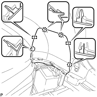
REMOVE FRONT DOOR SCUFF PLATE LH (for RHD)
-
Disengage the 4 claws, 2 guides and 4 clips, and remove the front door scuff plate LH.
-
-
REMOVE COWL SIDE TRIM SUB-ASSEMBLY RH (for LHD)
Tech Tips
Use the same procedure described for the LH side Click here.
-
REMOVE COWL SIDE TRIM SUB-ASSEMBLY LH (for RHD)
-
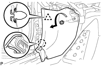
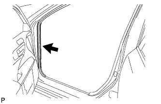
Remove the clip as shown in the illustration.
-
Disengage the clip and claw, and remove the cowl side trim sub-assembly LH.
-
-
DISCONNECT FRONT DOOR OPENING TRIM WEATHERSTRIP RH (for LHD)
Tech Tips
Use the same procedure described for the LH side Click here
-
DISCONNECT FRONT DOOR OPENING TRIM WEATHERSTRIP LH (for RHD)
-
Disconnect the front door opening trim weatherstrip.
-
Remove the residual weatherstrip sealant from the body of the vehicle using cleaner.
Note
Remove the sealant completely. Any residual sealant may transfer to other areas of the vehicle when removing/installing the interior parts.
-
-
REMOVE INSTRUMENT SIDE PANEL RH (for LHD)
-
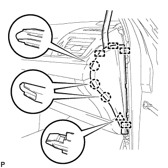
Using a moulding remover, disengage the 3 claws, clip and 4 guides, and remove the instrument side panel RH.
-
Disconnect the connector.
-
-
REMOVE INSTRUMENT SIDE PANEL LH (for RHD)
-
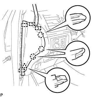
Using a moulding remover, disengage the 3 claws, clip and 4 guides, and remove the instrument side panel LH.
-
-
REMOVE NO. 2 INSTRUMENT PANEL UNDER COVER SUB-ASSEMBLY (for LHD)
-
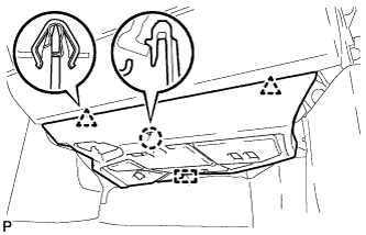
Disengage the 2 clips, claw and guide.
-
Disengage the clamp.
-
Disconnect the connector and remove the No. 2 instrument panel under cover sub-assembly.
-
-
REMOVE NO. 2 INSTRUMENT PANEL UNDER COVER SUB-ASSEMBLY (for RHD)
-
Disengage the 2 clips, claw and 2 guides.
-
Disengage the clamp.
-
Disconnect the connector and remove the No. 2 instrument panel under cover sub-assembly.
-
-
REMOVE LOWER NO. 2 INSTRUMENT PANEL AIRBAG ASSEMBLY
CAUTION:
When storing the lower No. 2 instrument panel airbag assembly, keep the airbag deployment side facing upward.
-
Check that the power switch is off.
-
Check that the cable is disconnected from the negative (-) auxiliary battery terminal.
CAUTION:
Wait at least 90 seconds after disconnecting the cable from the negative (-) auxiliary battery terminal to disable the SRS system.
-
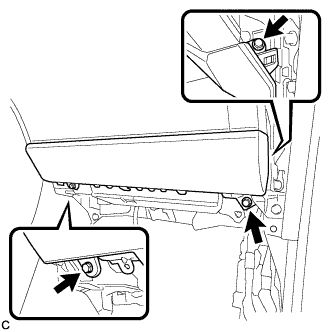
Remove the 3 bolts.
-
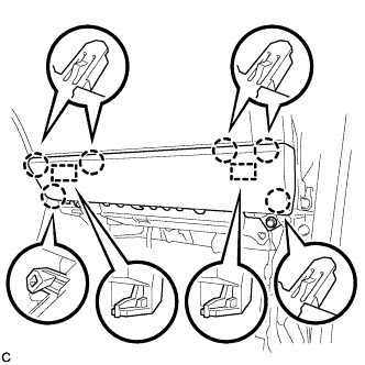
Disengage the 6 claws and 2 guides to separate the lower No. 2 instrument panel airbag assembly.
-
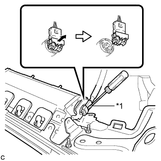
Text in Illustration *1 Protective Tape Using a screwdriver with the tip wrapped with protective tape, release the airbag connector lock.
-
Disconnect the airbag connector to remove the lower No. 2 instrument panel airbag assembly.
Note
When disconnecting any airbag connector, take care not to damage the airbag wire harness.
-
-
REMOVE GLOVE COMPARTMENT DOOR ASSEMBLY
-
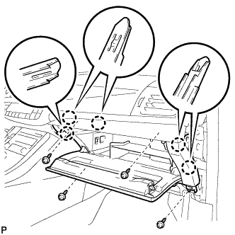
Remove the 4 screws <C>.
-
Disengage the 5 claws.
-
Disengage the clamp.
-
Disconnect the connector and remove the glove compartment door assembly.
-
-
REMOVE ECU INTEGRATION BOX RH (for LHD)
-
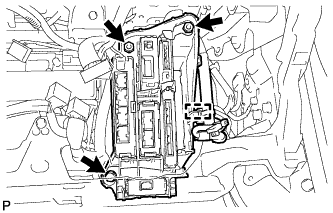
Disconnect each connector.
-
Disengage the clamp and disconnect the wire harness.
-
Remove the bolt, 2 nuts and ECU integration box RH.
-
-
REMOVE ECU INTEGRATION BOX LH (for RHD)
-
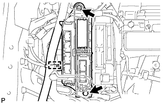
Disconnect each connector.
-
Disengage the clamp and disconnect the wire harness.
-
Remove the bolt, nut and ECU integration box LH.
-
-
REMOVE TRANSMISSION CONTROL ECU ASSEMBLY
-
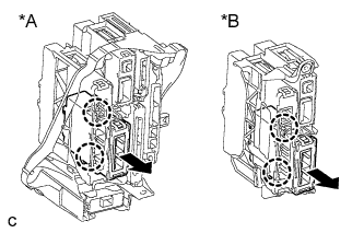
Text in Illustration *A for LHD *B for RHD Disengage the 2 claws and remove the transmission control ECU assembly from the ECU integration box.
-