REAR WHEEL ALIGNMENT ADJUSTMENT
Note
If the wheel alignment has been adjusted, and if suspension or underbody components have been removed/installed or replaced, be sure to perform the following initialization procedure in order for the system to function normally:
-
Perform zero point calibration of the yaw rate and acceleration sensor.
-
INSPECT TIRES
-
Check the tires for wear and proper inflation pressure.
Cold Tire Inflation Pressure Area Tire Size For driving under 160 km/h (100 mph) For driving at over 160 km/h (100 mph) Front
kPa (kgf/cm2, psi)
Rear
kPa (kgf/cm2, psi)
Front
kPa (kgf/cm2, psi)
Rear
kPa (kgf/cm2, psi)
Europe
(Countries that use WVTA)
195/65R15 91H 230 (2.3, 33)*1
270 (2.7 ,39)*2
250 (2.5, 36) 205/55R16 91V 220 (2.2, 32) 240 (2.4, 35) 215/45R17 87W 230 (2.3, 33) 220 (2.2, 32) 230 (2.3, 33) 220 (2.2, 32) Europe
(Countries that do not use WVTA)
195/65R15 91H 230 (2.3, 33) 250 (2.5, 36) 205/55R16 91V 220 (2.2, 32) 240 (2.4, 35) 215/45R17 87W 230 (2.3, 33) 220 (2.2, 32) 230 (2.3, 33) 220 (2.2, 32) GCC 205/55R16 91V 220 (2.2, 32) 240 (2.4, 35) China 195/65R15 91H 230 (2.3, 33) 250 (2.5, 36) 205/55R16 91V 220 (2.2, 32) 240 (2.4, 35) *1: Standard Pressure
*2: ECO Pressure
-
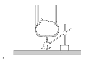
Using a dial indicator, check the runout of the tires.
Maximum tire runout 1.4 mm (0.0551 in.)
-
-
MEASURE VEHICLE HEIGHT
Note
-
Before inspecting the wheel alignment, adjust the vehicle height to the specified value.
-
Be sure to perform measurement on a level surface.
-
If it is necessary to go under the vehicle for measurement, confirm that the parking brake is applied and the vehicle is secured with chocks.
-
Inspect while the vehicle is unloaded.
-
The standard value shown here is a value that is used for adjusting the wheel alignment and does not indicate the height of an actual vehicle.
-
Bounce the vehicle up and down at the corners to stabilize the suspension.
-
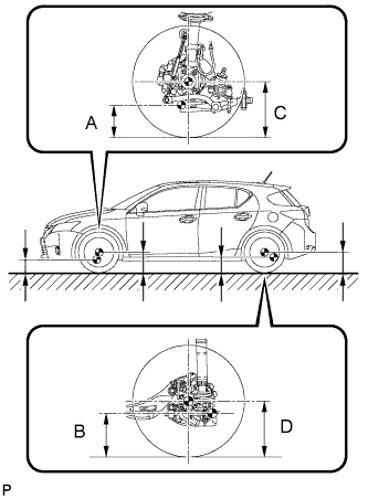
Measure the vehicle height.
-
A: Ground clearance of front lower No. 1 suspension arm bushing set bolt center
Measurement points:
-
B: Ground clearance of rear No. 2 suspension arm set bolt center
-
C: Ground clearance of front wheel center
-
D: Ground clearance of rear wheel center
Vehicle Height (Unloaded Vehicle) Tire Size Front C - A Rear D - B 195/65R15 112 mm (4.41 in.) 61 mm (2.40 in.) 205/55R16
215/45R17
(except sport)
104 mm (4.09 in.) *3
102 mm (4.02 in.)*1 *2
64 mm (2.52 in.) *3
61 mm (2.40 in.)*1 *2
205/55R16
215/45R17
(sport)
106 mm (4.17 in.) 59 mm (2.32 in.) *1: For Europe (Countries that use WVTA) except Turkey
*2: For Ukraine, Kazakhstan, Russia, Bosnia and Herzegovina, Croatia, Serbia
*3: Except for those indicated by *1 or *2.
-
-
-
INSPECT CAMBER
Note
Inspect while the vehicle is unloaded.
-
Text in Illustration *a Camber-caster-kingpin Gauge Install a camber-caster-kingpin gauge.
-
Inspect the camber.
Camber (Unloaded Vehicle) Camber Inclination Right-left Difference -1°00' +/- 0°45' (-1.00° +/- 0.75°) 0°45' (0.75°) or less Tech Tips
Camber is not adjustable. If the measurement is not within the specified range, inspect the suspension parts for damage and/or wear, and replace them if necessary.
-
-
INSPECT TOE-IN
Note
Inspect while the vehicle is unloaded.
-
Bounce the vehicle up and down at the corners to stabilize the suspension.
-
Release the parking brake and move the shift lever to N.
-
Push the vehicle straight ahead approximately 5 m (16.4 ft.). (Step A)
-
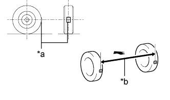
Text in Illustration *a Tread Center Mark *b Dimension B 
Front of the Vehicle Put tread center marks on the rearmost points of the rear wheels and measure the distance between the marks (dimension B).
-
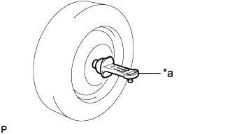
Slowly push the vehicle straight ahead to cause the rear wheels to rotate 180° using the rear tire valve as a reference point.
Tech Tips
Do not allow the wheels to rotate more than 180°. If the wheels rotate more than 180°, perform the procedure from Step A again.
-
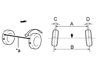
Text in Illustration *a Dimension A Front of the Vehicle Measure the distance between the tread center marks on the front side of the rear wheels (dimension A).
Toe-in (Unloaded Vehicle) Specified Condition Right-left Difference C + D: 0°12' +/- 0°12' ( 0.20° +/- 0.20°) 0°06' (0.10°) or less B - A: 2.0 +/- 2.0 mm (0.0787 +/- 0.0787 in.) 1.0 mm (0.0393 in.) or less Tech Tips
Measure "B - A" only when "C + D" cannot be measured.
If the toe-in is not within the specified range, adjust it at the rear No. 1 suspension arms.
-
-
ADJUST TOE-IN
-
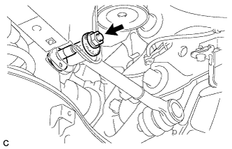
Loosen the nut of the rear No. 1 suspension arm assembly (at the rear suspension member side).
Note
Hold the rear suspension toe adjust cam sub-assembly while rotating the nut.
-
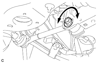
Rotate the rear suspension toe adjust cam sub-assembly to adjust the toe-in.
Toe-in (Unloaded Vehicle) Specified Condition Right-left Difference C + D: 0°12' +/- 0°12' ( 0.20° +/- 0.20°) 0°06' (0.10°) or less B - A: 2.0 +/- 2.0 mm (0.0787 +/- 0.0787 in.) 1.0 mm (0.0393 in.) or less Tech Tips
Rotating the rear suspension toe adjust cam sub-assembly by one notch changes the toe by approximately 3.3 mm (0.130 in.).
-
Tighten the nut of the rear No. 1 suspension arm assembly (at the rear suspension member side).
- Torque:
- 100 N*m { 1020 kgf*cm, 74 ft.*lbf }
Note
-
Hold the rear suspension toe adjust cam sub-assembly while rotating the nut.
-
Make sure that all tires of the vehicle are on the ground and the vehicle is unloaded.
-
-
PLACE FRONT WHEELS FACING STRAIGHT AHEAD
-
PERFORM YAW RATE AND ACCELERATION SENSOR CALIBRATION
-
PERFORM INITIALIZATION (w/ Height Control Sensor)
Note
Some systems need to be initialized after the wheel alignment is adjusted Click here.