GENERATOR CABLE REMOVAL
-
PRECAUTION
Note
After turning the power switch off, waiting time may be required before disconnecting the cable from the negative (-) auxiliary battery terminal. Therefore, make sure to read the disconnecting the cable from the negative (-) auxiliary battery terminal notices before proceeding with work Click here.
-
REMOVE REAR NO. 2 FLOOR BOARD
-
Remove the rear No. 2 floor board.
-
-
REMOVE REAR DECK FLOOR BOX
-
Remove the rear deck floor box.
-
-
REMOVE REAR NO. 3 FLOOR BOARD
-
Remove the rear No. 3 floor board.
-
-
REMOVE DECK FLOOR BOX RH
-
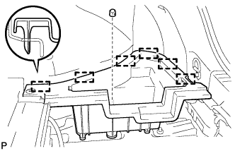
Remove the clip.
-
Disengage the 6 guides and remove the deck floor box RH.
-
-
REMOVE REAR FLOOR BOARD UPPER NO. 3 PLATE
-
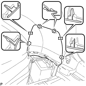
Disengage the 4 claws and 2 guides, and remove the rear floor board upper No. 3 plate.
-
-
DISCONNECT CABLE FROM NEGATIVE AUXILIARY BATTERY TERMINAL
Note
When disconnecting the cable, some systems need to be initialized after the cable is reconnected Click here.
-
REMOVE SERVICE PLUG GRIP
CAUTION:
-
Wear insulating gloves.
-
Remove the service plug grip to interrupt the high voltage circuit at the time of inspection or repair.
-
Keep the removed service plug grip in your pocket to prevent other technicians from accidentally reconnecting it while you are servicing the vehicle.
-
High voltage wiring connectors are orange.
-
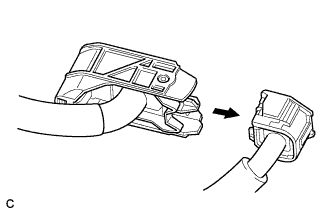
Wear insulated gloves and remove the service plug grip after sliding up the lever of the service plug grip as shown in the illustration.
CAUTION:
-
Keep the removed service plug grip in your pocket to prevent other technicians from accidentally reconnecting it while you are servicing the vehicle.
-
After removing the service plug grip, do not touch the high voltage connectors or terminals for 10 minutes.
Tech Tips
Waiting for at least 10 minutes is required to discharge the high-voltage capacitor inside the inverter with converter assembly.
-
-
-
REMOVE FRONT LOWER BUMPER ABSORBER
-
REMOVE NO. 1 ENGINE UNDER COVER
-
DRAIN COOLANT (for Engine)
for 2ZR-FXE: Click here
for 5ZR-FXE: Click here
-
DRAIN COOLANT (for Inverter)
Note
-
Do not reuse the drained coolant because it may contain foreign objects.
-
Collect the drained coolant and measure its volume to establish a benchmark. When adding coolant, make sure to add more coolant than the measured amount.
-
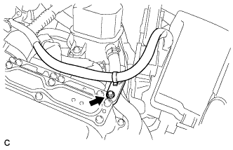
Remove the reserve tank cap.
CAUTION:
To avoid the danger of being burned, do not remove the reserve tank cap while the coolant for the inverter is still hot.
-
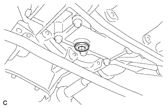
Using a hexagon wrench (10 mm), remove the drain plug indicated in the illustration and drain the coolant.
CAUTION:
Use caution when handling coolant immediately after driving or in summer because it may be hot.
-
Install the plug with a new gasket.
- Torque:
- 39 N*m { 397 kgf*cm, 29 ft.*lbf }
-
-
REMOVE INVERTER COVER ASSEMBLY LH (w/ Cover)
-
Remove the 2 clips
-
Disengage the claw and remove the inverter cover assembly LH.
-
-
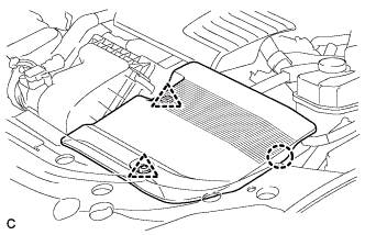
REMOVE RADIATOR SUPPORT OPENING COVER
-

Remove the 9 clips and radiator support opening cover (for 9 Clip Type).
-
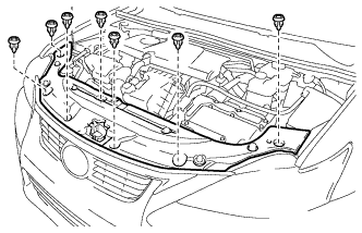
Remove the 7 clips and radiator support opening cover (for 7 Clip Type).
-
-
REMOVE NO. 1 INVERTER BRACKET
-
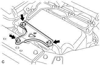
Remove the 3 bolts and No. 1 inverter bracket.
-
-
DISCONNECT ENGINE ROOM MAIN WIRE
-
Raise the lock lever and disconnect the inverter with converter connector.
-
Disconnect the engine wire from the engine room main wire.
-
Remove the bolt.
-
Remove the bolt, clamp and clip, and disconnect the engine room main wire.
-
-
REMOVE INVERTER COVER
CAUTION:
Wear insulating gloves.
-
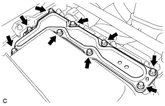
Remove the 9 bolts and inverter cover.
Note
Make sure to pull the inverter cover straight up, as a connector is connected to the bottom of the cover.
-
-
CHECK TERMINAL VOLTAGE
CAUTION:
Wear insulating gloves.
Note
Do not allow any foreign objects or water to enter the inverter with converter assembly.
-
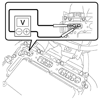
Using a voltmeter, measure the voltage between the terminals of the 2 phase connectors.
Standard voltage 0 V Tech Tips
Use measuring range of DC 750 V or more on the voltmeter.
-
-
DISCONNECT FRAME WIRE
CAUTION:
Wear insulating gloves.
Note
-
Insulate the disconnected terminals with insulating tape.
-
Cover the hole where the cable was connected with tape or equivalent (non-residue type) to prevent entry of foreign matter.
-
Disconnect the 2 harness clamps.
-
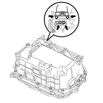
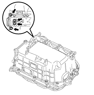
Remove the 4 bolts, and disconnect the frame wire (high voltage cables of the hybrid battery) from the inverter with converter assembly.
-
-
DISCONNECT GENERATOR CABLE
CAUTION:
Wear insulating gloves.
Note
-
Insulate the disconnected terminals with insulating tape.
-
Cover the hole where the cable was connected with tape or equivalent (non-residue type) to prevent entry of foreign matter.
-
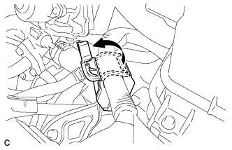
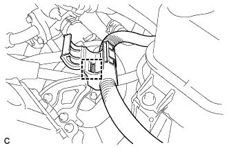
Turn back the wire harness cover and release the cable.
-
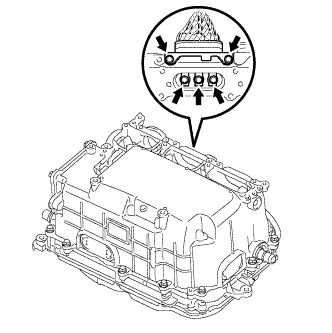
Remove the 5 bolts, and disconnect the high voltage cables of the generator cable (MG1) from the inverter with converter assembly.
-
-
DISCONNECT MOTOR CABLE
CAUTION:
Wear insulating gloves.
Note
-
Insulate the disconnected terminals with insulating tape.
-
Cover the hole where the cable was connected with tape or equivalent (non-residue type) to prevent entry of foreign matter.
-
Disconnect the harness clamp.
-
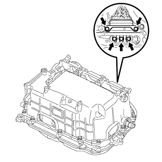
Remove the 5 bolts, and disconnect the high voltage cables of the motor cable (MG2) from the inverter with converter assembly.
-
-
DISCONNECT NO. 2 ENGINE WIRE
CAUTION:
Wear insulating gloves.
Note
-
Insulate the disconnected terminals with insulating tape.
-
Cover the hole where the cable was connected with tape or equivalent (non-residue type) to prevent entry of foreign matter.
-
Remove the 4 bolts, and disconnect the No. 2 engine wire (high voltage cables for the air conditioning compressor) from the inverter with converter assembly.
-
Disconnect the harness clamp.
-
-
INSTALL INVERTER COVER
-
Temporarily install the inverter cover with the 9 bolts to prevent any foreign objects or water from entering the inverter with converter assembly.
-
-
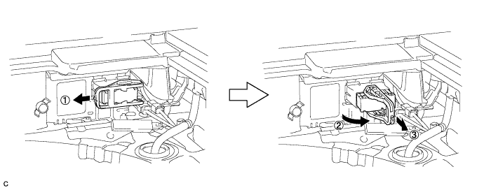
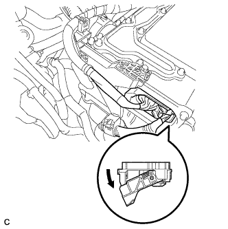
DISCONNECT NO. 2 ENGINE ROOM WIRE
-
Remove the relay block cover.
-
Release the 2 clamps, and remove the No. 1 relay block cover.
-
Remove the bolt from the No. 2 engine room wire.
-
Release the 2 claws, and disconnect the No. 2 engine room wire.
-
Connect the No. 2 engine room wire to the protector.
-
-
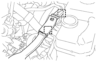
DISCONNECT WATER HOSE
-
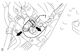
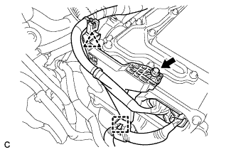
Text in Illustration *1 Retainer Release the retainer and disconnect the water hose from the inverter with converter assembly.
-
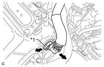
Text in Illustration *1 Retainer Release the retainer and disconnect the water hose from the inverter with converter assembly.
-
Disconnect the coolant hose from the inverter with converter assembly. Put a piece of cloth in the pipe and in the disconnected hose or cover the pipe and hose with plastic bags as shown in the illustration, so that foreign matter doesn't stick to the union or the inside of the connector and to prevent coolant from spilling near the inverter with converter assembly.
-
-
REMOVE INVERTER WITH CONVERTER ASSEMBLY
CAUTION:
Wear insulating gloves.
-
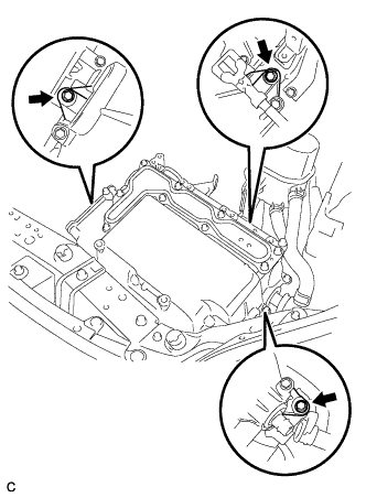
Remove the 3 bolts and inverter with converter assembly.
Note
-
Since the inverter with converter assembly is very heavy, 2 people are needed to remove the inverter with converter assembly. When removing the inverter with converter assembly, do not damage the parts around it.
-
To prevent damage, do not hold the inverter with converter assembly by the connectors.
-
To prevent damage due to static electricity, do not touch the terminals of the disconnected connectors.
-
-
Even after the coolant is drained, coolant remains in the inverter due to its internal structure. Therefore, seal or cover the pipes when removing the inverter so that coolant does not spill out.
-
-
REMOVE INVERTER RESERVE TANK ASSEMBLY (for 2ZR-FXE)
-

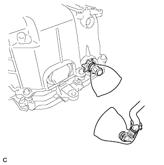
Remove the 2 bolts and separate the inverter reserve tank assembly.
-
-
REMOVE INVERTER RESERVE TANK ASSEMBLY (for 5ZR-FXE)
-
Remove the 2 bolts and separate the inverter reserve tank assembly.
-
-
REMOVE INVERTER TRAY BRACKET (for 2ZR-FXE)
-
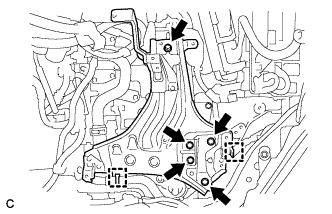
Separate the 2 clamps.
-
Remove the 5 bolts and inverter tray bracket.
-
-
REMOVE INVERTER TRAY BRACKET (for 5ZR-FXE)
-
Separate the 2 clamps.
-
Remove the 5 bolts and inverter tray bracket.
-
-
REMOVE RADIATOR PIPE
-
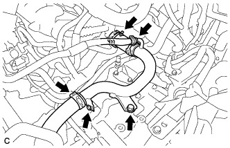
Disconnect the 3 clamps, No. 1 radiator hose, No. 4 water by-pass hose and No. 3 radiator hose.
-
Remove the 2 bolts and radiator pipe.
-
-
REMOVE GENERATOR CABLE
Note
Wear insulated gloves.
-
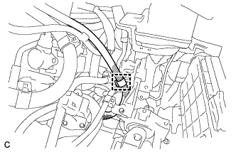
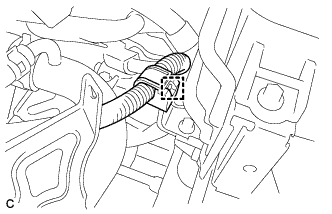
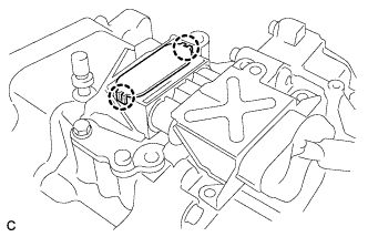
Disconnect the generator cable clamp from the motor cable bracket.
-
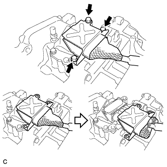
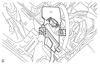
Remove the 3 bolts and slide the generator cable connector shell back.
-
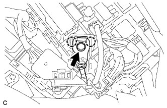
Disengage the 2 claws to remove the terminal cap.
-
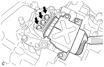
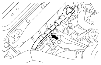
Remove the 3 bolts and generator cable from the hybrid transaxle assembly.
-