DYNAMIC RADAR CRUISE CONTROL SYSTEM, Diagnostic DTC:C1A05
| DTC Code | DTC Name |
|---|---|
| C1A05 | Stop Light Switch Circuit |
DESCRIPTION
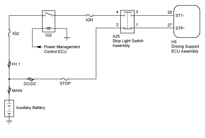
When the brake pedal is depressed, the stop light switch assembly sends a brake pedal operation signal to the driving support ECU assembly. After reception of this signal, the driving support ECU assembly cancels the dynamic radar cruise control system. When the driving support ECU assembly detects a problem in the stop light switch assembly circuit, DTC C1A05 is stored.
| DTC No. | DTC Detection Condition | Trouble Area |
|---|---|---|
| C1A05 | When the power switch is on (IG) or the cruise control main switch (ON-OFF button) is on, the driving support ECU assembly detects a malfunction in the signal received from the stop light switch assembly. |
|
WIRING DIAGRAM
INSPECTION PROCEDURE
Tech Tips
Inspect the fuses for circuits related to this system before performing the following inspection procedure.
PROCEDURE
-
CHECK HARNESS AND CONNECTOR (STOP LIGHT SWITCH ASSEMBLY POWER SOURCE)
-
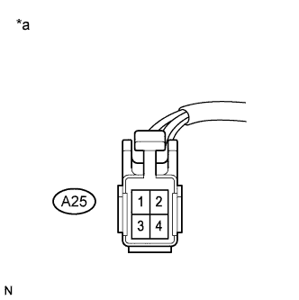
Text in Illustration *a Front view of wire harness connector
(to Stop Light Switch Assembly)
Disconnect the A25 stop light switch assembly connector.
-
Measure the voltage according to the value(s) in the table below.
Standard Voltage Tester Connection Condition Specified Condition A25-2 - Body ground Always 11 to 14 V
NG 
REPAIR OR REPLACE HARNESS OR CONNECTOR
OK 
-
-
CHECK HARNESS AND CONNECTOR (STOP LIGHT SWITCH ASSEMBLY POWER SOURCE)
-
Text in Illustration *a Front view of wire harness connector
(to Stop Light Switch Assembly)
Disconnect the A25 stop light switch assembly connector.
-
Turn the power switch on (IG).
-
Measure the voltage according to the value(s) in the table below.
Standard Voltage Tester Connection Condition Specified Condition A25-4 - Body ground Power switch on (IG) 11 to 14 V
NG
REPAIR OR REPLACE HARNESS OR CONNECTOR
OK
-
-
INSPECT STOP LIGHT SWITCH ASSEMBLY
-
Remove the stop light switch assembly Click here.
-
Inspect the stop light switch assembly Click here.
NG
REPLACE STOP LIGHT SWITCH ASSEMBLY Click here
OK
-
-
CHECK HARNESS AND CONNECTOR (STOP LIGHT SWITCH ASSEMBLY - DRIVING SUPPORT ECU ASSEMBLY)
-
Disconnect the A25 stop light switch assembly connector.
-
Disconnect the H5 driving support ECU assembly connector.
-
Measure the resistance according to the value(s) in the table below.
Standard Resistance Tester Connection Switch Condition Specified Condition A25-3 - H5-28 (ST1-) Always Below 1 Ω A25-1 - H5-27 (STP-) Always Below 1 Ω A25-3 or H5-28 (ST1-) - Body ground Always 10 kΩ or higher A25-1 or H5-27 (STP-) - Body ground Always 10 kΩ or higher
NG
REPAIR OR REPLACE HARNESS OR CONNECTOR
OK 
REPLACE DRIVING SUPPORT ECU ASSEMBLY Click here
-