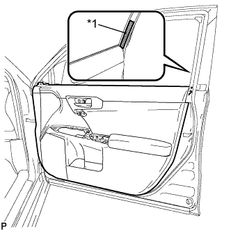
BLACK OUT TAPE (for Front Door) REMOVAL
-
PRECAUTION
Note
After turning the power switch off, waiting time may be required before disconnecting the cable from the negative (-) battery terminal. Therefore, make sure to read the disconnecting the cable from the negative (-) battery terminal notice before proceeding with work Click here.
-
REMOVE REAR NO. 2 FLOOR BOARD
-
Remove the rear No. 2 floor board.
-
-
REMOVE REAR DECK FLOOR BOX
-
Remove the rear deck floor box.
-
-
REMOVE REAR NO. 3 FLOOR BOARD
-
Remove the rear No. 3 floor board.
-
-
REMOVE DECK FLOOR BOX RH
-
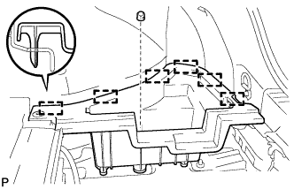
Remove the clip.
-
Disengage the 6 guides and remove the deck floor box RH.
-
-
REMOVE REAR FLOOR BOARD UPPER NO. 3 PLATE
-
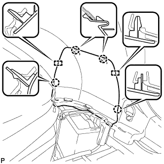
Disengage the 4 claws and 2 guides, and remove the rear floor board upper No. 3 plate.
-
-
DISCONNECT CABLE FROM NEGATIVE BATTERY TERMINAL
Note
When disconnecting the cable, some systems need to be initialized after the cable is reconnected Click here.
-
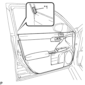
REMOVE FRONT DOOR INSIDE HANDLE BEZEL PLUG
-
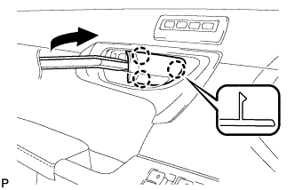
Using a moulding remover, disengage the 3 claws and remove the front door inside handle bezel plug as shown in the illustration.
-
-
REMOVE FRONT DOOR LOWER FRAME BRACKET GARNISH
-
Disengage the clip and claw, and remove the front door lower frame bracket garnish.
-
-
REMOVE POWER WINDOW REGULATOR MASTER SWITCH ASSEMBLY WITH FRONT DOOR ARMREST BASE PANEL (for Driver Side)
-
Using a moulding remover, disengage the 3 clips, 7 claws and 2 guides as shown in the illustration.
-
Disconnect the connector and remove the power window regulator master switch assembly with front door armrest base panel.
-
-
REMOVE DOOR ARMREST COVER (for Driver Side)
-
Remove the door armrest cover.
-
-
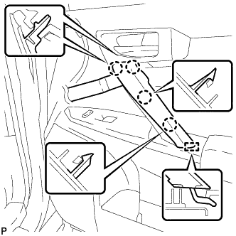
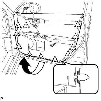
REMOVE FRONT DOOR TRIM BOARD SUB-ASSEMBLY (for Driver Side)
-
Text in Illustration *1 Protective Tape Put protective tape around the front door panel.
-
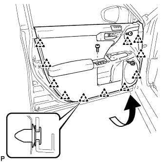
Remove the 3 screws.
-
Using a clip remover, disengage the 11 clips.
-
Pull out the front door trim board sub-assembly in the direction indicated by the arrow in the illustration.
-
Raise the front door trim board sub-assembly and remove it.
-
w/ Seat Position Memory System:
-
Disconnect the connector.
-
-
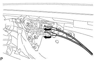
Disconnect the front door lock remote control cable assembly and front door inside locking cable assembly.
-
-
REMOVE DOOR ASSIST GRIP COVER (for Front Passenger Side)
-
Using a moulding remover, disengage the 4 claws and guide to remove the door assist grip cover.
-
-
REMOVE DOOR ASSIST GRIP ASSEMBLY (for Front Passenger Side)
-
Remove the 2 screws.
-
Disengage the 3 guides and remove the door assist grip assembly.
-
-
REMOVE POWER WINDOW REGULATOR SWITCH ASSEMBLY WITH FRONT DOOR ARMREST BASE PANEL (for Front Passenger Side)
-
Using a moulding remover, disengage the 3 clips, 8 claws and 4 guides as shown in the illustration.
-
Disconnect each connector and remove the power window regulator switch assembly with front door armrest base panel.
-
-
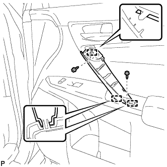
REMOVE FRONT DOOR TRIM BOARD SUB-ASSEMBLY (for Front Passenger Side)
-
Text in Illustration *1 Protective Tape Put protective tape around the front door panel.
-
Remove the 2 screws.
-
Using a clip remover, disengage the 11 clips.
-
Pull out the front door trim board sub-assembly in the direction indicated by the arrow in the illustration.
-
Raise the front door trim board sub-assembly and remove the front door trim board sub-assembly .
-
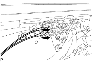
Disconnect the front door lock remote control cable assembly and front door inside locking cable assembly.
-
-
REMOVE FRONT DOOR TRIM BRACKET (for Driver Side)
-
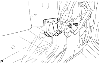
Remove the 2 screws and front door trim bracket.
-
-
REMOVE FRONT DOOR TRIM BRACKET (for Front Passenger Side)
-
Remove the 2 screws and front door trim bracket.
-
-
REMOVE FRONT DOOR SERVICE HOLE COVER
-
Remove the front door service hole cover.
Tech Tips
Remove any remaining butyl tape from the door.
-
-
REMOVE FRONT DOOR GLASS SUB-ASSEMBLY
-
Remove the grommet.
-
Connect the cable to the negative (-) battery terminal.
-
Connect the power window regulator master switch assembly and move the front door glass sub-assembly so that the door glass bolts can be seen.
-
Disconnect the cable from the negative (-) battery terminal.
Note
When disconnecting the cable, some systems need to be initialized after the cable is reconnected Click here.
-
Disconnect the power window regulator master switch assembly.
-
Remove the 2 bolts.
Note
After the bolts are removed, do not allow the door glass to fall.
-
Remove the front door glass sub-assembly as indicated by the arrows, in the order shown in the illustration.
Note
Do not damage the door glass.
-
-
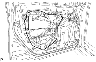
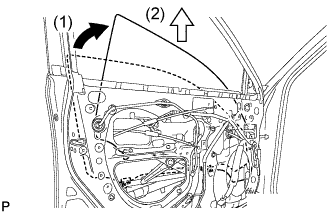
REMOVE FRONT DOOR GLASS RUN
-
Remove the front door glass run.
-
-
REMOVE FRONT DOOR FRONT LOWER FRAME UPPER COVER
-
Text in Illustration *1 Double-sided Tape Disengage the 2 clips and remove the front door front lower frame upper cover.
-
-
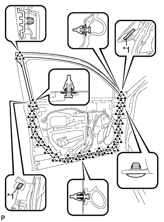
REMOVE FRONT DOOR BELT MOULDING ASSEMBLY
-
Text in Illustration *1 Protective Tape Put protective tape around the front door belt moulding assembly.
-
Text in Illustration *1 Protective Tape Using a screwdriver with the tip wrapped with protective tape, disengage the 7 claws and remove the front door belt moulding assembly.
-
-
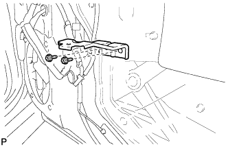
REMOVE FRONT DOOR CHECK ASSEMBLY
-
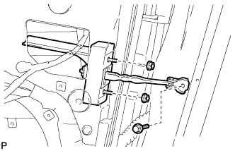
Remove the bolt, 2 nuts and front door check assembly.
-
-
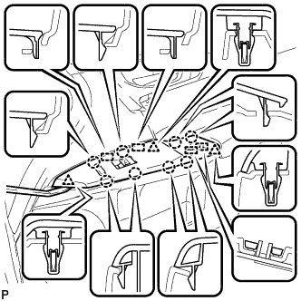
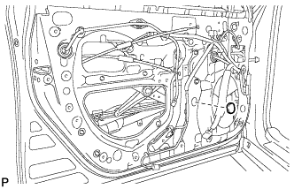
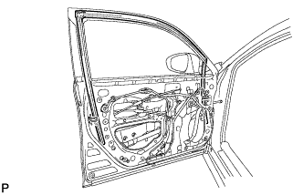
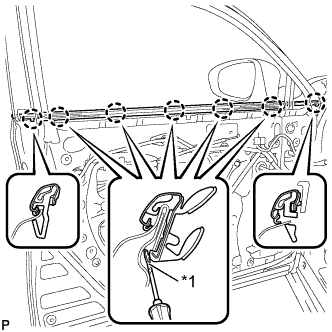
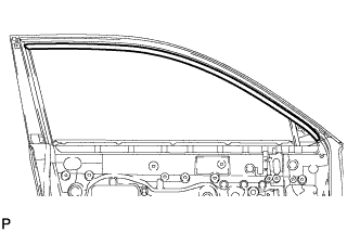
REMOVE FRONT DOOR WEATHERSTRIP
-
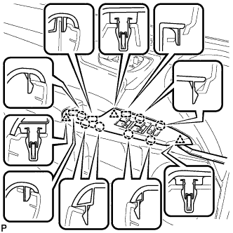
Text in Illustration *1 Double-sided Tape Using a clip remover, disengage the 20 clips and remove the front door weatherstrip.
-
-
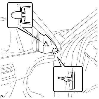
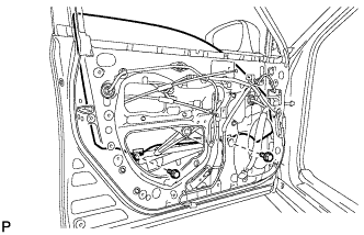
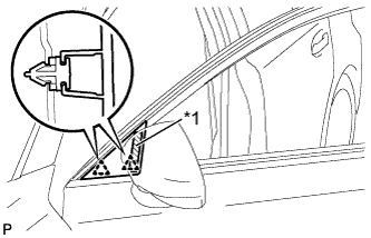
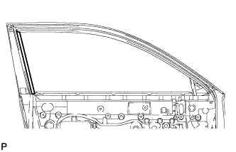
REMOVE DOOR FRAME GARNISH
-
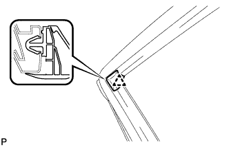
Disengage the clip and remove the door frame garnish.
Tech Tips
This garnish needs to be replaced with a new one because the clip will break when removing it.
-
-
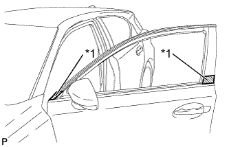
REMOVE FRONT DOOR OUTSIDE STRIPE
-
Using a heat light, heat the front door outside stripe and vehicle body.
Heating Temperature Item Temperature Vehicle Body and Front Door Outside Stripe 40 to 60°C (104 to 140°F) Note
Do not heat the vehicle body excessively.
-
Pull back on one of the ends of the front door outside stripe to remove it.
Tech Tips
When pulling on the stripe, pull it parallel to the body.
-
-
REMOVE FRONT DOOR REAR OUTSIDE STRIPE
-
Using a heat light, heat the front door rear outside stripe and vehicle body.
Heating Temperature Item Temperature Vehicle Body and Front Door Rear Outside Stripe 40 to 60°C (104 to 140°F) Note
Do not heat the vehicle body excessively.
-
Pull back on one of the ends of the front door rear outside stripe to remove it.
Tech Tips
When pulling on the stripe, pull it parallel to the body.
-