STOP LIGHT SWITCH INSTALLATION
-
INSTALL STOP LIGHT SWITCH ASSEMBLY
-
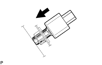
Insert the stop light switch assembly until the rod hits the pedal.
Note
When inserting the stop light switch assembly, support the pedal from behind so that the pedal is not pushed in.
-
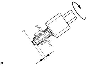
Make a quarter turn clockwise to install the stop light switch assembly.
- Torque:
- 1.5 N*m { 15 kgf*cm, 13 in.*lbf, or less }
Note
When inserting the stop light switch assembly, support the pedal from behind so that the pedal is not pushed in.
-
Connect the connector.
-
Check the protrusion of the rod.
Protrusion of the rod 1.5 to 2.5 mm (0.0591 to 0.0984 in.) If the protrusion is not as specified, adjust it.
Note
Do not depress the brake pedal.
-
-
INSTALL NO. 1 INSTRUMENT PANEL UNDER COVER SUB-ASSEMBLY (for LHD)
-
Connect each connector.
-
Engage the clamp.
-
Engage the clip.
-
Install the No. 1 instrument panel under cover sub-assembly with the 2 screws <E>.
-
-
INSTALL NO. 1 INSTRUMENT PANEL UNDER COVER SUB-ASSEMBLY (for RHD)
-
Connect each connector.
-
Engage the clamp.
-
Engage the 2 clips.
-
Install the No. 1 instrument panel under cover sub-assembly with the screw <E>.
-