LIGHTING SYSTEM Headlight Beam Level Control Actuator Circuit
DESCRIPTION
The headlight leveling ECU assembly actuates the headlight leveling motor according to vehicle conditions.
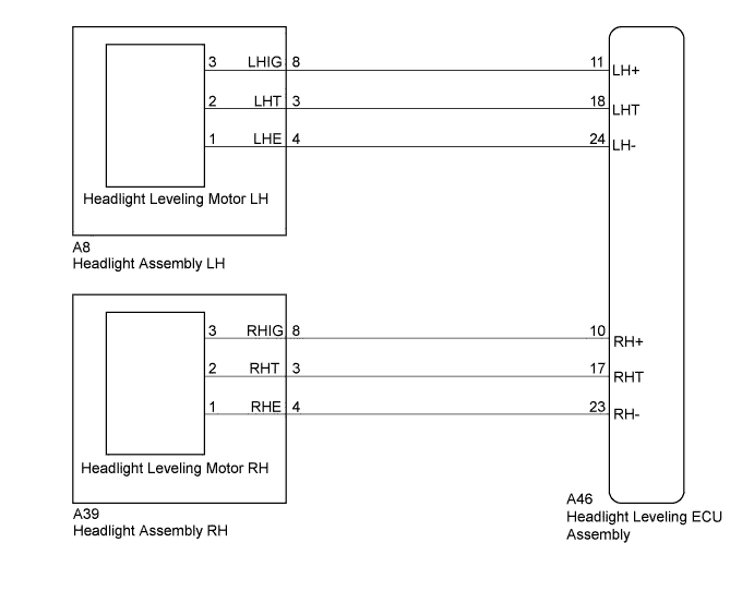
WIRING DIAGRAM
INSPECTION PROCEDURE
PROCEDURE
-
PERFORM ACTIVE TEST USING INTELLIGENT TESTER
-
Connect the intelligent tester to the DLC3.
-
Turn the power switch on (READY).
-
Turn the intelligent tester on.
-
Enter the following menus: Body / HL Auto Leveling / Active Test.
-
Check that the leveling motors operate.
HL Auto Leveling Tester Display Test Part Control Range Diagnostic Note Drive The Leveling Motor UP Leveling motor upward operation ON/OFF ON: Move up
OFF: Stop
Drive The Leveling Motor DOWN Leveling motor downward operation ON/OFF ON: Move down
OFF: Stop
OK Headlight leveling motors operate normally.
NG 
CHECK HARNESS AND CONNECTOR (HEADLIGHT ASSEMBLY - HEADLIGHT LEVELING ECU ASSEMBLY) Click here
OK 
PROCEED TO NEXT SUSPECTED AREA SHOWN IN PROBLEM SYMPTOMS TABLE Click here
-
-
CHECK HARNESS AND CONNECTOR (HEADLIGHT ASSEMBLY - HEADLIGHT LEVELING ECU ASSEMBLY)
-
Disconnect the A46 headlight leveling ECU assembly connector.
-
Disconnect the A8 or A39 headlight assembly connector.
-
Measure the resistance according to the value(s) in the table below.
Standard Resistance LH Side Tester Connection Condition Specified Condition A8-8 (LHIG) - 3 Always Below 1 Ω A8-3 (LHT) - 2 Always Below 1 Ω A8-4 (LHE) - 1 Always Below 1 Ω A8-8 (LHIG) - Body ground Always 10 kΩ or higher A8-3 (LHT) - Body ground Always 10 kΩ or higher A8-4 (LHE) - Body ground Always 10 kΩ or higher RH Side Tester Connection Condition Specified Condition A39-8 (RHIG) - 3 Always Below 1 Ω A39-3 (RHT) - 2 Always Below 1 Ω A39-4 (RHE) - 1 Always Below 1 Ω A39-8 (RHIG) - Body ground Always 10 kΩ or higher A39-3 (RHT) - Body ground Always 10 kΩ or higher A39-4 (RHE) - Body ground Always 10 kΩ or higher
NG 
REPAIR OR REPLACE HARNESS OR CONNECTOR
OK 
-
-
CHECK HEADLIGHT ASSEMBLY (HEADLIGHT ASSEMBLY - HEADLIGHT LEVELING MOTOR)
-
Disconnect the LH side or RH side headlight leveling motor connector.
-
Measure the resistance according to the value(s) in the table below.
Standard Resistance LH Side Tester Connection Condition Specified Condition A46-18 (LHT) - A8-3 (LHT) Always Below 1 Ω A46-11 (LH+) - A8-8 (LHIG) Always Below 1 Ω A46-24 (LH-) - A8-4 (LHE) Always Below 1 Ω A46-18 (LHT) - Body ground Always 10 kΩ or higher A46-11 (LH+) - Body ground Always 10 kΩ or higher A46-24 (LH-) - Body ground Always 10 kΩ or higher RH Side Tester Connection Condition Specified Condition A46-17 (RHT) - A39-3 (RHT) Always Below 1 Ω A46-10 (RH+) - A39-8 (RHIG) Always Below 1 Ω A46-23 (RH-) - A39-4 (RHE) Always Below 1 Ω A46-17 (RHT) - Body ground Always 10 kΩ or higher A46-10 (RH+) - Body ground Always 10 kΩ or higher A46-23 (RH-) - Body ground Always 10 kΩ or higher
NG
REPLACE HEADLIGHT ASSEMBLY Click here
OK
-
-
REPLACE HEADLIGHT LEVELING MOTOR
-
Replace the headlight leveling motor with a new or a known good one Click here.
-
Perform the active test of the leveling motors.
OK Headlight leveling motors operate normally. Result Result Proceed to NG A OK (for LHD) B OK (for RHD) C
B
REPLACE HEADLIGHT LEVELING ECU ASSEMBLY Click here
C
REPLACE HEADLIGHT LEVELING ECU ASSEMBLY Click here
A
END (HEADLIGHT LEVELING MOTOR WAS DEFECTIVE)
-