LIGHTING SYSTEM Hazard Warning Switch Circuit
DESCRIPTION
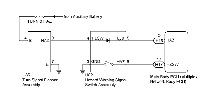
The main body ECU (multiplex network body ECU) receives the hazard switch ON signal and controls the operation of the flasher relay assembly.
WIRING DIAGRAM
INSPECTION PROCEDURE
PROCEDURE
-
READ VALUE USING INTELLIGENT TESTER
-
Connect the intelligent tester to the DLC3.
-
Turn the power switch on (IG).
-
Turn the intelligent tester on.
-
Enter the following menus: Body / Main Body / Data List.
-
Read the display on the intelligent tester.
Main Body Tester Display Measurement Item/Range Normal Condition Diagnostic Note Hazard Switch Hazard switch signal/ON or OFF ON: Hazard switch on
OFF: Hazard switch off
- OK Normal conditions listed above are displayed.
NG 
INSPECT HAZARD WARNING SIGNAL SWITCH ASSEMBLY Click here
OK 
-
-
PERFORM ACTIVE TEST USING INTELLIGENT TESTER
-
Connect the intelligent tester to the DLC3.
-
Turn the power switch on (IG).
-
Turn the intelligent tester on.
-
Enter the following menus: Body / Main Body / Active Test.
-
Check that the hazard lights illuminate.
Main Body Tester Display Test Part Control Range Diagnostic Note Hazard Hazard warning lights ON/OFF - OK Hazard lights illuminate.
NG
CHECK HARNESS AND CONNECTOR (TURN & HAZ FUSE - TURN SIGNAL FLASHER ASSEMBLY) Click here
OK 
PROCEED TO NEXT SUSPECTED AREA SHOWN IN PROBLEM SYMPTOMS TABLE Click here
-
-
INSPECT HAZARD WARNING SIGNAL SWITCH ASSEMBLY
-
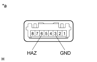
Text in Illustration *a Component without harness connected
(Hazard Warning Signal Switch Assembly)
Remove the hazard warning signal switch assembly Click here.
-
Measure the resistance according to the value(s) in the table below.
Standard Resistance Tester Connection Switch Condition Specified Condition 6 (HAZ) - 3 (GND) Hazard switch on Below 1 Ω 6 (HAZ) - 3 (GND) Hazard switch off 10 kΩ or higher
NG 
REPLACE HAZARD WARNING SIGNAL SWITCH ASSEMBLY Click here
OK
-
-
CHECK HARNESS AND CONNECTOR (HAZARD WARNING SIGNAL SWITCH - MAIN BODY ECU)
-
Disconnect the H17 main body ECU (multiplex network body ECU) connector.
-
Measure the resistance according to the value(s) in the table below.
Standard Resistance Tester Connection Condition Specified Condition H82-6 (HAZ) - H17-17 (HZSW) Always Below 1 Ω H82-6 (HAZ) - Body ground Always 10 kΩ or higher H82-3 (GND) - Body ground Always Below 1 Ω
NG
REPAIR OR REPLACE HARNESS OR CONNECTOR
OK
REPLACE MAIN BODY ECU (MULTIPLEX NETWORK BODY ECU) Click here
-
-
CHECK HARNESS AND CONNECTOR (TURN & HAZ FUSE - TURN SIGNAL FLASHER ASSEMBLY)
-
Disconnect the H35 turn signal flasher assembly connector.
-
Measure the voltage according to the value(s) in the table below.
Standard Voltage Tester Connection Condition Specified Condition H35-4 (B) - Body ground Always 11 to 14 V -
Measure the resistance according to the value(s) in the table below.
Standard Resistance Tester Connection Condition Specified Condition H35-7 (E) - Body ground Always Below 1 Ω
NG
REPAIR OR REPLACE HARNESS OR CONNECTOR
OK
-
-
INSPECT TURN SIGNAL FLASHER ASSEMBLY
-
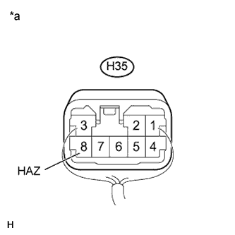
Text in Illustration *a Component without harness connected
(Turn Signal Flasher Assembly)
Reconnect the H35 turn signal flasher assembly connector.
-
Measure the voltage according to the value(s) in the table below.
Standard Voltage Tester Connection Switch Condition Specified Condition H35-8 (HAZ) - Body ground Hazard switch off 9 V or higher H35-8 (HAZ) - Body ground Hazard switch on Below 1 V Result Result Proceed to NG (when the hazard switch on) A NG (when the hazard switch off) B OK B
B
REPLACE TURN SIGNAL FLASHER ASSEMBLY Click here
A
-
-
CHECK HARNESS AND CONNECTOR (TURN SIGNAL FLASHER - HAZARD WARNING SIGNAL SWITCH ASSEMBLY)
-
Disconnect the H35 turn signal flasher assembly connector.
-
Disconnect the H82 hazard warning signal switch assembly connector.
-
Measure the resistance according to the value(s) in the table below.
Standard Resistance Tester Connection Condition Specified Condition H35-8 (HAZ) - H82-4 (FLSW) Always Below 1 Ω H35-8 (HAZ) - Body ground Always 10 kΩ or higher
NG
REPAIR OR REPLACE HARNESS OR CONNECTOR
OK
-
-
CHECK HARNESS AND CONNECTOR (HAZARD WARNING SIGNAL SWITCH ASSEMBLY - MAIN BODY ECU)
-
Disconnect the H16 main body ECU (multiplex network body ECU) connector.
-
Measure the resistance according to the value(s) in the table below.
Standard Resistance Tester Connection Condition Specified Condition H82-5 (LJB) - H16-3 (HAZ) Always Below 1 Ω H82-5 (LJB) - Body ground Always 10 kΩ or higher
NG
REPAIR OR REPLACE HARNESS OR CONNECTOR
OK
-
-
INSPECT HAZARD WARNING SIGNAL SWITCH ASSEMBLY
-
Reconnect the H35 turn signal flasher assembly connector.
-
Reconnect the H82 hazard warning signal switch assembly connector.
-
Reconnect the H16 main body ECU (multiplex network body ECU) connector.
-
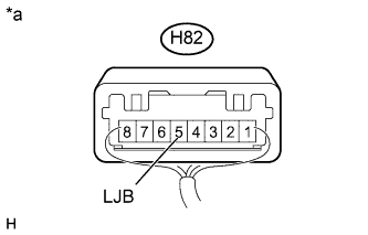
Text in Illustration *a Component with harness connected
(Hazard Warning Signal Switch Assembly)
Measure the voltage according to the value(s) in the table below.
Standard Voltage Tester Connection Switch Condition Specified Condition H82-5 (LJB) - Body ground Power switch off 11 to 14 V
NG
REPLACE HAZARD WARNING SIGNAL SWITCH ASSEMBLY Click here
OK
REPLACE MAIN BODY ECU (MULTIPLEX NETWORK BODY ECU) Click here
-