AIR FUEL RATIO SENSOR REMOVAL

-
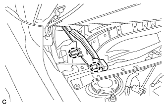
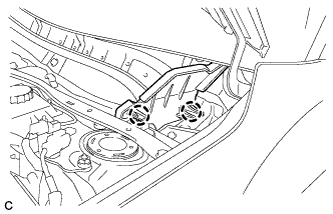
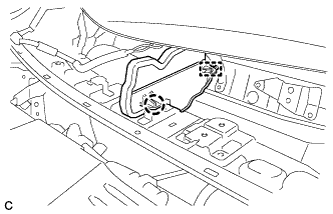
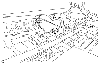
REMOVE WINDSHIELD WIPER MOTOR AND LINK ASSEMBLY
-
REMOVE NO. 1 HEATER AIR DUCT SPLASH SHIELD SEAL (for LHD)
-
Disengage the 2 claws and remove the No. 1 heater air duct splash shield seal.
-
-
REMOVE NO. 1 HEATER AIR DUCT SPLASH SHIELD SEAL (for RHD)
-
Disengage the 2 claws and remove the No. 1 heater air duct splash shield seal.
-
-
REMOVE NO. 2 HEATER AIR DUCT SPLASH SHIELD SEAL (for LHD)
-
Disengage the claw and guide, and remove the No. 2 heater air duct splash shield seal.
-
-
REMOVE NO. 2 HEATER AIR DUCT SPLASH SHIELD SEAL (for RHD)
-
Disengage the claw and guide, and remove the No. 2 heater air duct splash shield seal.
-
-
REMOVE COWL BODY MOUNTING REINFORCEMENT LH (for LHD)
-
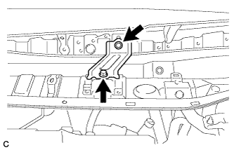
Remove the 2 bolts and cowl body mounting reinforcement LH.
-
-
REMOVE COWL BODY MOUNTING REINFORCEMENT RH (for RHD)
-
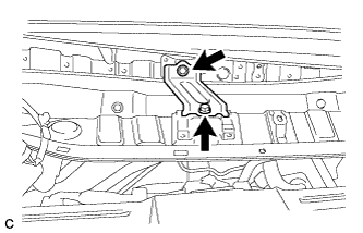
Remove the 2 bolts and cowl body mounting reinforcement RH.
-
-
REMOVE OUTER COWL TOP PANEL SUB-ASSEMBLY (for LHD)
-
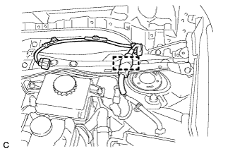
Disengage the clamp and separate the wire harness.
-
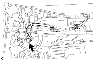
w/ Wiper Deicer:
Disengage the 3 clamps, disconnect the connector and separate the wire harness.
-
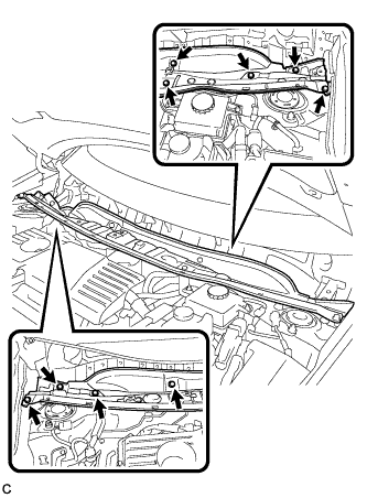
Remove the 9 bolts and outer cowl top panel sub-assembly.
-
-
REMOVE OUTER COWL TOP PANEL SUB-ASSEMBLY (for RHD)
-
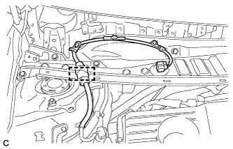
Disengage the clamp and separate the wire harness.
-
w/ Wiper Deicer:
Disengage the 3 clamps, disconnect the connector and separate the wire harness.
-
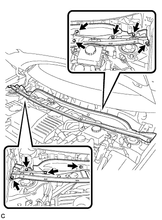
Remove the 9 bolts and outer cowl top panel sub-assembly.
-
-
REMOVE NO. 2 CYLINDER HEAD COVER
-
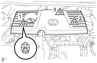
Remove the 3 clips and No. 2 cylinder head cover.
Note
-
Disengage the clips in the order shown in the illustration.
-
When disengaging clip 3, hold the end of the cover behind clip 3 and lift the cover straight up.
-
Attempting to disengage both front and rear clips at the same time may cause the cover to break.
-
Pull the cover straight up to remove. Attempting to pull the cover forward or pull it up by holding the left and right ends may cause the cover to break.
-
-
-
REMOVE AIR FUEL RATIO SENSOR NO.2
-
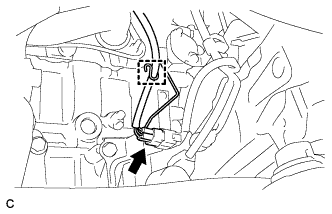
Disconnect the air fuel ratio sensor connector and clamp.
-
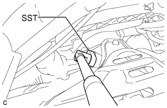
Using SST, remove the air fuel ratio sensor.
- SST
- 09224-00010
-