| DTC Code | DTC Name |
|---|---|
| ECM Power Source Circuit |
DESCRIPTION
When the power switch is turned on (IG), auxiliary battery voltage is applied to IGSW of the ECM. The output signal from the MREL terminal of the ECM causes a current to flow to the coil, closing the contacts of the No. 2 integration relay (EFI MAIN relay) and supplying power to either terminal +B and +B2 of the ECM.
INSPECTION PROCEDURE
-
After turning the power switch off, waiting time may be required before disconnecting the cable from the negative (-) auxiliary battery terminal. Therefore, make sure to read the disconnecting the cable from the negative (-) auxiliary battery terminal notices before proceeding with work (Click here).
-
Inspect the fuses for circuits related to this system before performing the following inspection procedure.
PROCEDURE
- Click here
CHECK HARNESS AND CONNECTOR (ECM - BODY GROUND)
-
Disconnect the ECM connector.
-
Measure the resistance according to the value(s) in the table below.
Standard Resistance Tester Connection Condition Specified Condition D27-104 (E1) - Body ground Always Below 1 Ω
- OKClick here
- NGClick here
-
- Click here
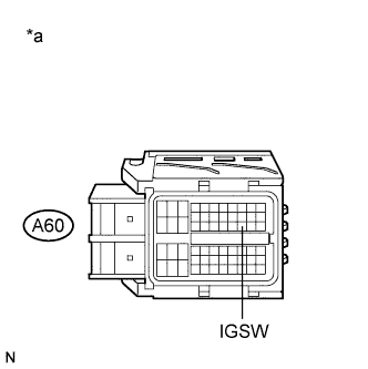
INSPECT ECM (IGSW VOLTAGE)
-
Disconnect the ECM connector.
-
Turn the power switch on (IG).
-
Measure the voltage according to the value(s) in the table below.
Standard Voltage Tester Connection Switch Condition Specified Condition A60-28 (IGSW) - Body ground Power switch on (IG) 11 to 14 V Table 1. Text in Illustration *a Front view of wire harness connector
(to ECM)
- OKClick here
- NGClick here
-
- Click here
INSPECT NO. 2 INTEGRATION RELAY (EFI MAIN RELAY)
-
Inspect the No. 2 integration relay (EFI MAIN relay) (Click here).
- OKClick here
- NGClick here
-
- Click here
CHECK HARNESS AND CONNECTOR (NO. 2 INTEGRATION RELAY (EFI MAIN RELAY) - ECM)
-
Remove the No. 2 integration relay (EFI MAIN relay) from the engine room relay block.
-
Disconnect the No. 2 integration relay connector.
-
Disconnect the ECM connector.
-
Measure the resistance according to the value(s) in the table below.
Standard Resistance Tester Connection Condition Specified Condition 1B-4 - A60-1 (+B2) Always Below 1 Ω 1B-4 - A60-2 (+B) Always Below 1 Ω 1B-2 - A60-6 (MREL) Always Below 1 Ω 1B-4 or A60-1 (+B2) - Body ground Always 10 kΩ or higher 1B-4 or A60-2 (+B) - Body ground Always 10 kΩ or higher 1B-2 or A60-6 (MREL) - Body ground Always 10 kΩ or higher
- OKClick here
- NGClick here
-
- Click here
CHECK HARNESS AND CONNECTOR (NO. 2 INTEGRATION RELAY (EFI MAIN RELAY) - AUXILIARY BATTERY)
-
Remove the No. 2 integration relay (EFI MAIN relay) from the engine room relay block.
-
Disconnect the No. 2 integration relay connector.
-
Disconnect the negative (-) auxiliary battery terminal.
-
Disconnect the positive (+) auxiliary battery terminal.
-
Measure the resistance according to the value(s) in the table below.
Standard Resistance Tester Connection Condition Specified Condition 1C-1 - Positive (+) auxiliary battery terminal Always Below 1 Ω 1C-1 or Positive (+) auxiliary battery terminal - Body ground Always 10 kΩ or higher
- OKClick here
- NGClick here
-
- Click here
CHECK HARNESS AND CONNECTOR (NO. 2 INTEGRATION RELAY (EFI MAIN RELAY) - BODY GROUND)
-
Remove the No. 2 integration relay (EFI MAIN relay) from the engine room relay block.
-
Disconnect the No. 2 integration relay connector.
-
Measure the resistance according to the value(s) in the table below.
Standard Resistance Tester Connection Condition Specified Condition 1B-3 - Body ground Always Below 1 Ω
- OKClick here
- NGClick here
-
- Click here
PROCEED TO NEXT SUSPECTED AREA SHOWN IN PROBLEM SYMPTOMS TABLEClick here
- Click here
INSPECT NO. 2 INTEGRATION RELAY (IG2 RELAY)
-
Inspect the No. 2 integration relay (IG2 relay) (Click here).
- OKClick here
- NGClick here
-
- Click here
CHECK HARNESS AND CONNECTOR (NO. 2 INTEGRATION RELAY (IG2 RELAY) - ECM)
-
Disconnect the ECM connector.
-
Remove the No. 2 integration relay (IG2 relay) from the engine room relay block.
-
Disconnect the No. 2 integration relay connector.
-
Measure the resistance according to the value(s) in the table below.
Standard Resistance Tester Connection Condition Specified Condition 1A-4 - A60-28 (IGSW) Always Below 1 Ω 1A-4 or A60-28 (IGSW) - Body ground Always 10 kΩ or higher
- OKClick here
- NGClick here
-
- Click here
CHECK HARNESS AND CONNECTOR (NO. 2 INTEGRATION RELAY (IG2 RELAY) - AUXILIARY BATTERY)
-
Remove the No. 2 integration relay (IG2 relay) from the engine room relay block.
-
Disconnect the No. 2 integration relay connector.
-
Disconnect the negative (-) auxiliary battery terminal.
-
Disconnect the positive (+) auxiliary battery terminal.
-
Measure the resistance according to the value(s) in the table below.
Standard Resistance Tester Connection Condition Specified Condition 1C-1 - Positive (+) auxiliary battery terminal Always Below 1 Ω 1C-1 or Positive (+) auxiliary battery terminal - Body ground Always 10 kΩ or higher
- OKClick here
- NGClick here
-
- Click here
CHECK HARNESS AND CONNECTOR (NO. 2 INTEGRATION RELAY (IG2 RELAY) - BODY GROUND)
-
Remove the No. 2 integration relay (IG2 relay) from the engine room relay block.
-
Disconnect the No. 2 integration relay connector.
-
Measure the resistance according to the value(s) in the table below.
Standard Resistance Tester Connection Condition Specified Condition 1A-3 - Body ground Always Below 1 Ω
- OKClick here
- NGClick here
-
- Click here
CHECK HARNESS AND CONNECTOR (POWER MANAGEMENT CONTROL ECU - INTEGRATION RELAY (IG2 RELAY))
-
Remove the No. 2 integration relay (IG2 relay) from the engine room relay block.
-
Disconnect the No. 2 integration relay connector.
-
Disconnect the power management control ECU connector.
-
Measure the resistance according to the value(s) in the table below.
Standard Resistance Tester Connection Condition Specified Condition A20-2 (IG2D) - 1A-2 Always Below 1 Ω
- OKClick here
- NGClick here
-
- Click here
CHECK ENTRY AND START SYSTEM (FOR START FUNCTION)Click here
- Click here
REPAIR OR REPLACE HARNESS OR CONNECTOR
- Click here
REPLACE NO. 2 INTEGRATION RELAYClick here
- Click here
REPAIR OR REPLACE HARNESS OR CONNECTOR
- Click here
REPAIR OR REPLACE HARNESS OR CONNECTOR
- Click here
REPAIR OR REPLACE HARNESS OR CONNECTOR
- Click here
REPLACE NO. 2 INTEGRATION RELAY (IG2 RELAY)Click here
- Click here
REPAIR OR REPLACE HARNESS OR CONNECTOR
- Click here
REPAIR OR REPLACE HARNESS OR CONNECTOR
- Click here
REPAIR OR REPLACE HARNESS OR CONNECTOR
- Click here
REPAIR OR REPLACE HARNESS OR CONNECTOR