SFI SYSTEM (w/ EGR System), Diagnostic DTC:P0401
| DTC Code | DTC Name |
|---|---|
| P0401 | Exhaust Gas Recirculation Flow Insufficient Detected |
DESCRIPTION
Based on the driving conditions, the ECM regulates the volume of exhaust gas that is recirculated to the engine's combustion chambers and thus lowers the combustion temperature to reduce NOx emissions. The ECM monitors signals such as engine speed, coolant temperature, electric load, and vehicle speed. When the EGR permission conditions are fulfilled, the ECM controls the opening of the EGR valve linearly through signals to the EGR step motor.
| DTC No. | DTC Detection Condition | Trouble Area |
|---|---|---|
| P0401 | Change in intake manifold pressure is small when the EGR valve is opened and closed during idle fuel cut operation (2 trip detection logic). |
|
MONITOR DESCRIPTION
The ECM monitors the pressure inside the intake manifold while opening and closing the EGR valve during fuel cut operation. If there is no change in the manifold absolute pressure sensor value, the ECM interprets this as a malfunction in the EGR valve assembly, illuminates the MIL and stores the DTC (2 trip detection logic).
MONITOR STRATEGY
| Required Sensors/Components (Main) | EGR valve assembly, manifold absolute pressure sensor |
| Required Sensors/Components (Related) | Engine coolant temperature sensor, vehicle speed sensor |
| Frequency of Operation | Once per driving cycle |
TYPICAL ENABLING CONDITIONS
| Engine speed | 950 to 1600 rpm |
| Vehicle speed | 20 km/h (12.4 mph) or more |
| Intake air temperature | -10°C (14°F) or higher |
TYPICAL MALFUNCTION THRESHOLDS
| Manifold pressure change | Less than 1.0 kPa (7.5 mmHg) |
| At engine speed | 1050 rpm |
CONFIRMATION DRIVING PATTERN
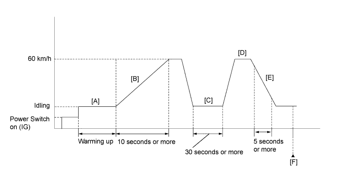
-
Connect the intelligent tester to the DLC3.
-
Turn the power switch on (IG) and turn the tester on.
-
Clear the DTCs (even if no DTCs are stored, perform the clear DTC operation).
-
Turn the power switch off and wait for 30 seconds.
-
Turn the power switch on (IG) and turn the tester on.
-
Put the engine in inspection mode (maintenance mode) Click here.
-
Start the engine and warm it up until the engine coolant temperature reaches 75°C (167°F) or higher [A].
Tech Tips
The A/C switch and all accessory switches should be off and shift lever in P.
-
Accelerate the vehicle to 60 km/h (37 mph) or more by depressing the accelerator pedal for at least 10 seconds [B].
CAUTION:
When performing the confirmation driving pattern, obey all speed limits and traffic laws.
-
Idle the engine for 30 seconds or more [C].
-
Accelerate the vehicle to 60 km/h (37 mph) with the shift lever in B [D].
-
Perform fuel cut operation for 5 seconds or more, with the accelerator pedal fully released [E].
CAUTION:
When performing the confirmation driving pattern, obey all speed limits and traffic laws.
Tech Tips
When fuel cut is operating "Idle Fuel Cut" in Data List is ON.
-
Enter the following menus: Powertrain / Engine and ECT / DTC [F].
-
Read the pending DTCs.
Tech Tips
-
If a pending DTC is output, the system is malfunctioning.
-
If a pending DTC is not output, perform the following procedure.
-
-
Enter the following menus: Powertrain / Engine and ECT / Utility / All Readiness.
-
Input the DTC: P0401.
-
Check the DTC judgment result.
Tester Display Description NORMAL
-
DTC judgment completed
-
System normal
ABNORMAL
-
DTC judgment completed
-
System abnormal
INCOMPLETE
-
DTC judgment not completed
-
Perform driving pattern after confirming DTC enabling conditions
UNKNOWN
-
Unable to perform DTC judgment
-
Number of DTCs which do not fulfill DTC preconditions has reached ECU's memory limit
Tech Tips
-
If the judgment result shows NORMAL, the system is normal.
-
If the judgment result shows ABNORMAL, the system has a malfunction.
-
If the DTC judgment result is INCOMPLETE or UNKNOWN, perform steps [D] and [F] again.
-
INSPECTION PROCEDURE
Tech Tips
-
By using the Control the EGR Step Position Active Test, the operation of the EGR valve can be checked.
-
If the EGR valve is normal and is opened using the Active Test, the Data List value changes as follows.
Data List Change in Data List when Number of Steps is Increased Using Control the EGR Step Position Active Test MAP Pressure rises -
Read freeze frame data using the intelligent tester. The ECM records vehicle and driving condition information as freeze frame data the moment a DTC is stored. When troubleshooting, freeze frame data can help determine if the vehicle was moving or stationary, if the engine was warmed up or not, if the air fuel ratio was lean or rich, and other data from the time the malfunction occurred.
PROCEDURE
-
CHECK ANY OTHER DTCS OUTPUT (IN ADDITION TO P0401)
-
Connect the intelligent tester to the DLC3.
-
Turn the power switch on (IG).
-
Turn the tester on.
-
Enter the following menus: Powertrain / Engine and ECT / DTC.
-
Read the DTC.
Result Result Proceed to DTC P0401 is output A DTC P0401 and other DTCs are output B Tech Tips
If any DTCs other than P0401 are output, troubleshoot those DTCs first.
B 
GO TO DTC CHART Click here
A 
-
-
PERFORM ACTIVE TEST USING INTELLIGENT TESTER (CONTROL THE EGR STEP POSITION)
-
Connect the intelligent tester to the DLC3.
-
Turn the power switch on (IG).
-
Turn the tester on.
-
Put the engine in inspection mode (maintenance mode) Click here.
-
Start the engine and warm it up until the engine coolant temperature reaches 75°C (167°F) or higher.
Tech Tips
The A/C switch and all accessory switches should be off.
-
Enter the following menus: Powertrain / Engine and ECT / Active Test / Control the EGR Step Position / Data List / All Data / Throttle Idle Position and MAP.
-
Confirm that the Throttle Idle Position is ON and check the MAP value in the Data List while performing the Active Test.
Note
-
Do not leave the EGR valve open for 10 seconds or more during the Active Test.
-
Be sure to return the EGR valve to step 0 when the Active Test is completed.
-
Do not open the EGR valve 30 steps or more during the Active Test.
OK MAP change in response to EGR step position when Throttle Idle Position is ON in Data List. Standard - EGR Step Position (Active Test) 0 Steps 0 to 30 Steps MAP
(Data List)
(EGR valve is fully closed) MAP value is at least +10 kPa (75 mmHg) higher than when EGR valve is fully closed Tech Tips
-
While performing the Active Test, if the increase in the value of MAP is small, the EGR valve assembly may be a malfunctioning.
-
Even if the EGR valve assembly is malfunctioning, rough idling or an increase in the value of MAP may occur while performing the Active Test. However, the amount that the value of MAP increases will be smaller than normal.
-
NG 
REPLACE EGR VALVE ASSEMBLY Click here
OK
-
-
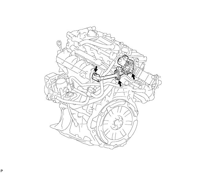
INSPECT EGR VALVE ASSEMBLY
-
Check if the EGR valve are clogged with deposits.
-
Check if the EGR valve is closed.
OK EGR valve is closed and no deposits. Result Result Proceed to Outside of standard range A Within standard range B
B
CHECK FOR DEPOSIT (INTAKE PORT TO EGR VALVE ASSEMBLY) Click here
A
-
-
REPLACE EGR VALVE ASSEMBLY
-
Replace the EGR valve assembly Click here.
NEXT
-
-
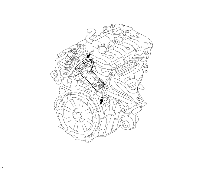
CHECK FOR DEPOSIT (INTAKE PORT TO EGR VALVE ASSEMBLY)
-
Check for exhaust leaks at each connection point.
-
Check for cracks, damage, and clogs in the pipes between the intake manifold and the EGR valve assembly.
-
This check may require the removal of components.
-
Check if there is a built-up of deposits in the EGR valve of pipes.
OK No deposits.
NG
REPAIR OR REPLACE MALFUNCTIONING PARTS, COMPONENT AND AREA
OK
-
-
CHECK FOR DEPOSIT (EXHAUST MANIFOLD SUB-ASSEMBLY TO EGR VALVE ASSEMBLY)
-
Check for exhaust leaks at each connection point.
-
Check for cracks, damage, and clogs in the pipes between the exhaust manifold sub-assembly and the EGR valve assembly.
-
This check may require the removal of components.
-
Check if there is a built-up of deposits in the EGR valve of pipes.
OK No deposits.
NG
REPAIR OR REPLACE MALFUNCTIONING PARTS, COMPONENT AND AREA
OK
-
-
INSPECT EGR WITH COOLER PIPE SUB-ASSEMBLY
-
Check for blockage of the EGR with cooler pipe sub-assembly.
NG
REPLACE EGR WITH COOLER PIPE SUB-ASSEMBLY Click here
OK
-
-
READ VALUE USING INTELLIGENT TESTER (MANIFOLD ABSOLUTE PRESSURE SENSOR)
-
Connect the intelligent tester to the DLC3.
-
Turn the power switch on (IG).
-
Turn the tester on.
-
Enter the following menus: Powertrain / Engine and ECT / Data List / All Data / MAP.
-
Read the MAP value.
Standard Switch Condition Tester Display Power switch on (IG) 80 to 110 kPa (600 to 825 mmHg) -
Put the engine in inspection mode (maintenance mode) Click here.
-
Start the engine and warm it up until the engine coolant temperature reaches 75°C (167°F) or higher.
-
Enter the following menus: Powertrain / Engine and ECT / Data List / Throttle Idle Position and MAP.
-
Confirm that the Throttle Idle Position is ON and check the engine idling condition and MAP when idling the engine with the A/C switch and all accessory switches should be off and shift lever in N or the P position.
Standard Engine Condition Tester Display Idling 20 to 40 kPa (150 to 300 mmHg) Result Result Proceed to NG A OK B
B
CONFIRM WHETHER MALFUNCTION HAS BEEN SUCCESSFULLY REPAIRED Click here
A
-
-
CHECK INTAKE SYSTEM
-
Check the intake system for vacuum leaks Click here.
OK No leaks in intake system.
NG
REPAIR OR REPLACE INTAKE SYSTEM
OK
-
-
REPLACE MANIFOLD ABSOLUTE PRESSURE SENSOR
-
Replace the manifold absolute pressure sensor Click here.
NEXT
-
-
CONFIRM WHETHER MALFUNCTION HAS BEEN SUCCESSFULLY REPAIRED
-
Connect the intelligent tester to the DLC3.
-
Turn the power switch on (IG).
-
Turn the tester on.
-
Clear the DTCs Click here.
-
Turn the power switch off and wait for 30 seconds.
-
Drive the vehicle in accordance with the driving pattern described in the Confirmation Driving Pattern.
-
Enter the following menus: Powertrain / Engine and ECT / DTC / Pending.
-
Read the pending DTCs.
Tech Tips
-
If the pending DTC is output, the system is malfunctioning.
-
If a pending DTC is not output, perform the following procedure.
-
-
Enter the following menus: Powertrain / Engine and ECT / Utility / All Readiness.
-
Input the DTC: P0401.
-
Check the DTC judgment result.
Tester Display Description NORMAL
-
DTC judgment completed
-
System normal
ABNORMAL
-
DTC judgment completed
-
System abnormal
INCOMPLETE
-
DTC judgment not completed
-
Perform driving pattern after confirming DTC enabling conditions
UNKNOWN
-
Unable to perform DTC judgment
-
Number of DTCs which do not fulfill DTC preconditions has reached ECU's memory limit
-
NEXT 
END
-