SFI SYSTEM (w/ EGR System), Diagnostic DTC:P0107, P0108
| DTC Code | DTC Name |
|---|---|
| P0107 | Manifold Absolute Pressure / Barometric Pressure Circuit Low Input |
| P0108 | Manifold Absolute Pressure / Barometric Pressure Circuit High Input |
DESCRIPTION
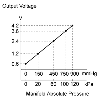
The manifold absolute pressure sensor detects pressure inside the intake manifold as an absolute pressure with a built-in sensor and outputs a voltage. Based on the voltage from the vacuum sensor, the ECM controls the air fuel ratio and corrects any errors in the pressure sensor due to changes in pressure.
| DTC No. | DTC Detecting Condition | Trouble Area |
|---|---|---|
| P0107 | The output voltage from the manifold absolute pressure sensor below 0.5 V for 0.5 seconds (1 trip detection logic). |
|
| P0108 | The output voltage from the manifold absolute pressure sensor higher than 4.5 V for 0.5 seconds (1 trip detection logic). |
|
Tech Tips
When DTC P0107 or P0108 is detected, check the manifold absolute pressure by selecting Powertrain / Engine and ECT / Data List / MAP on the intelligent tester.
| Manifold Absolute Pressure (kPa) | Malfunction |
|---|---|
| Approximately 0 kPa |
|
| 130 kPa or higher |
|
MONITOR DESCRIPTION
The ECM monitors the sensor voltage and uses this value to calculate the manifold absolute pressure. When the sensor output voltage deviates from the normal operating range, the ECM interprets this as a malfunction in the manifold absolute pressure sensor and sets a DTC.
Example:
When the sensor output voltage remains below 0.5 V, or higher than 4.5 V for 0.5 seconds, the ECM sets a DTC.
MONITOR STRATEGY
| Frequency of Operation | Continuous |
CONFIRMATION DRIVING PATTERN
-
Put the engine in inspection mode (maintenance mode) Click here.
-
Start the engine and wait for 5 seconds or more.
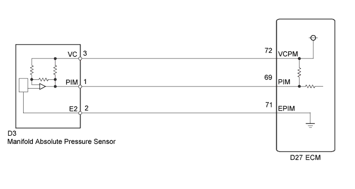
WIRING DIAGRAM
INSPECTION PROCEDURE
Tech Tips
Read freeze frame data using the intelligent tester. The ECM records vehicle and driving condition information as freeze frame data the moment a DTC is stored. When troubleshooting, freeze frame data can help determine if the vehicle was moving or stationary, if the engine was warmed up or not, if the air fuel ratio was lean or rich, and other data from the time the malfunction occurred.
PROCEDURE
-
READ VALUE USING INTELLIGENT TESTER (MAP)
-
Connect the intelligent tester to the DLC3.
-
Turn the power switch on (IG).
-
Turn the tester on.
-
Enter the following menus: Powertrain / Engine and ECT / Data List / MAP.
-
Read the MAP value.
OK Same value as the actual atmospheric pressure. Tech Tips
-
Standard atmospheric pressure is 101 kPa (758 mmHg). For every 100 m (328 ft.) increase in altitude, pressure drops by 1 kPa (7.5 mmHg). The pressure also varies due to the weather (high atmospheric pressure, low atmospheric pressure).
-
Also, check "Atmosphere Pressure" in the Data List.
-
NG 
CHECK TERMINAL VOLTAGE (MANIFOLD ABSOLUTE PRESSURE SENSOR) Click here
OK 
CHECK FOR INTERMITTENT PROBLEMS Click here
-
-
CHECK TERMINAL VOLTAGE (MANIFOLD ABSOLUTE PRESSURE SENSOR)
-
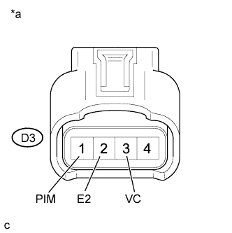
Text in Illustration *a Front view of wire harness connector
(to Manifold Absolute Pressure Sensor)
Disconnect the manifold absolute pressure sensor connector.
-
Turn the power switch on (IG).
-
Measure the voltage according to the value(s) in the table below.
Standard Voltage Tester Connection Switch Condition Specified Condition D3-3 (VC) - D3-2 (E2) Power switch on (IG) 4.5 to 5.5 V D3-1 (PIM) - D3-2 (E2) Power switch on (IG) 3.0 to 5.0 V Result Result Proceed to Outside standard range A Within standard range B
B
REPLACE MANIFOLD ABSOLUTE PRESSURE SENSOR Click here
A 
-
-
CHECK HARNESS AND CONNECTOR (MANIFOLD ABSOLUTE PRESSURE SENSOR - ECM)
-
Disconnect the manifold absolute pressure sensor connector.
-
Disconnect the ECM connector.
-
Measure the resistance according to the value(s) in the table below.
Standard Resistance Tester Connection Condition Specified Condition D3-3 (VC) - D27-72 (VCPM) Always Below 1 Ω D3-2 (E2) - D27-71 (EPIM) Always Below 1 Ω D3-1 (PIM) - D27-69 (PIM) Always Below 1 Ω D3-3 (VC) or D27-72 (VCPM) - Body ground Always 10 kΩ or higher D3-1 (PIM) or D27-69 (PIM) - Body ground Always 10 kΩ or higher
NG 
REPAIR OR REPLACE HARNESS OR CONNECTOR
OK
REPLACE ECM Click here
-
-
REPLACE MANIFOLD ABSOLUTE PRESSURE SENSOR
-
Replace the manifold absolute pressure sensor Click here.
NEXT
-
-
CHECK WHETHER DTC OUTPUT RECURS (P0107 OR P0108)
-
Connect the intelligent tester to the DLC3.
-
Turn the power switch on (IG) and turn the tester on.
-
Clear the DTCs.
-
Drive the vehicle in accordance with the driving pattern described in the Confirmation Driving Pattern.
-
Enter the following menus: Powertrain / Engine and ECT / DTC.
-
Read the DTCs.
Result Result Proceed to DTC is not output A DTC P0107 or P0108 is output B
B
REPLACE ECM Click here
A
END
-