EXHAUST PIPE GAS CONTROL ACTUATOR INSTALLATION
-
INSTALL EXHAUST PIPE GAS CONTROL ACTUATOR SUB-ASSEMBLY
-
Text in Illustration *A w/ Pin Top Plate *B w/o Pin Top Plate Clean the installation surfaces and bolt holes of the exhaust pipe gas control actuator sub-assembly and front exhaust pipe assembly.
Note
Make sure no foreign matter enters the cooling system when the exhaust pipe gas control actuator sub-assembly is removed.
-
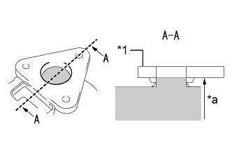
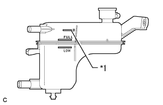
Text in Illustration *1 Flange *a Fill Up 
Coolant If the engine coolant spilled when removing the front exhaust pipe assembly, add engine coolant up to the bottom edge of the flange as shown in the illustration.
Tech Tips
If a large amount of air enters the cooling system, the load on the engine water pump assembly will increase.
-
w/o Pin Top Plate:
-
Text in Illustration *1 Small Insulator Using needle nose pliers, slightly tilt the small insulator in the direction shown by the arrow in the illustration to secure enough space to install the No. 2 exhaust pipe heat insulator.
Note
Depending on the date of vehicle production, some vehicles are not equipped with the small insulator.
-
-
Text in Illustration *A w/ Pin Top Plate *B w/o Pin Top Plate *1 No. 2 Exhaust Pipe Heat Insulator *2 Front Exhaust Pipe Assembly Set the No. 2 exhaust pipe heat insulator on the front exhaust pipe assembly.
Note
Confirm that the No. 2 exhaust pipe heat insulator is installed in the correct position.
-
w/o Pin Top Plate:
-
Text in Illustration *1 Small Insulator Tilt the small insulator back toward the No. 2 exhaust pipe heat insulator.
Note
Depending on the date of vehicle production, some vehicles are not equipped with the small insulator.
-
-
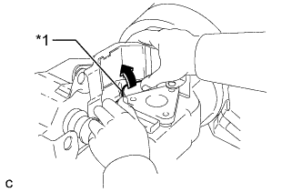
Text in Illustration *a Vehicle Front Lift the rear side of the No. 2 exhaust pipe heat insulator to allow the exhaust pipe gas control actuator sub-assembly to be installed below the flange on the No. 2 exhaust pipe heat insulator.
-
w/ Pin Top Plate:
-
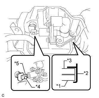
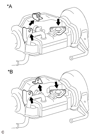
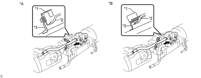
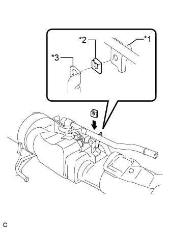
Text in Illustration *1 Front Exhaust Pipe Assembly *2 No. 2 Exhaust Pipe Heat Insulator *3 Exhaust Pipe Gas Control Actuator Sub-assembly *4 Pin Top Plate *5 Hook Loosely install the exhaust pipe gas control actuator sub-assembly, confirm the exhaust pipe gas control actuator sub-assembly is installed below the flange on the No. 2 exhaust pipe heat insulator and that the hook is engaged with the valve pin.
-
-
w/o Pin Top Plate:
-
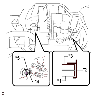
Text in Illustration *1 Front Exhaust Pipe Assembly *2 No. 2 Exhaust Pipe Heat Insulator *3 Exhaust Pipe Gas Control Actuator Sub-assembly *4 Valve Pin *5 Hook Loosely install the exhaust pipe gas control actuator sub-assembly, confirm the exhaust pipe gas control actuator sub-assembly is installed below the flange on the No. 2 exhaust pipe heat insulator and that the hook is engaged with the valve pin.
-
-
Loosely install the 3 bolts several threads.
-
Text in Illustration *1 Exhaust By-pass Pipe *2 O-ring Apply clean coolant to the O-ring.
Note
Do not damage the O-ring or allow it to become contaminated with foreign matter during work.
-
Install the exhaust by-pass pipe to the exhaust pipe gas control actuator sub-assembly.
Text in Illustration *A w/o Exhaust Pipe Plate *B w/ Exhaust Pipe Plate *1 Front Exhaust Pipe Assembly *2 No. 2 Exhaust Pipe Heat Insulator *3 Exhaust By-pass Pipe - - Note
-
Make sure to insert the front exhaust pipe assembly into the exhaust pipe gas control actuator as far as possible.
-
Confirm that the front exhaust pipe assembly, exhaust by-pass pipe and No. 2 exhaust pipe heat insulator are positioned correctly.
-
When reusing the exhaust by-pass pipe, inspect the O-ring.
-
If the O-ring has scratches or cuts, replace the exhaust by-pass pipe.
-
Make sure that the O-ring and the fitting section of the exhaust pipe gas control actuator sub-assembly are free of oil or foreign matter.
-
Do not touch the O-ring or fitting section of the exhaust pipe gas control actuator sub-assembly.
-
-
w/ Pin Top Plate:
-
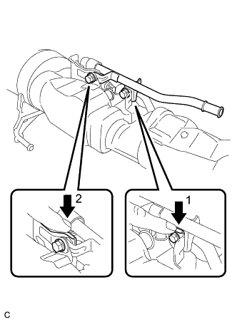
Install the 2 bolts in the order shown in the illustration.
- Torque:
- 8.5 N*m { 87 kgf*cm, 75 in.*lbf }
-
-
w/ Exhaust Pipe Plate:
-
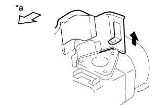
Text in Illustration *a Vehicle Front Press in the No. 2 exhaust pipe heat insulator to align the installation holes of the exhaust by-pass pipe and No. 2 exhaust pipe heat insulator.
-
Text in Illustration *1 Exhaust By-pass Pipe *2 Exhaust Pipe Plate *3 Front Exhaust Pipe Assembly Insert the exhaust pipe plate between the exhaust by-pass pipe and front exhaust pipe assembly.
-
While holding down the No. 2 exhaust pipe heat insulator and exhaust pipe plate, fully tighten the 2 bolts in the order shown in the illustration.
- Torque:
- 8.5 N*m { 87 kgf*cm, 75 in.*lbf }
Note
If the procedure is not followed correctly, malfunctions or coolant leaks from the O-ring may occur.
-
-
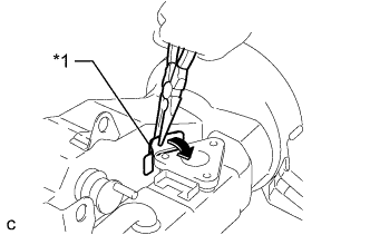
Text in Illustration *A w/ Pin Top Plate *B w/o Pin Top Plate *1 Valve Plate *a Insertion direction Confirm that the valve plate is positioned correctly by pressing the plate.
Tech Tips
If the valve plate is not positioned correctly, the final exhaust pipe gas control actuator sub-assembly position may be difficult to achieve.
-
w/ Pin Top Plate:
-
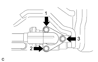
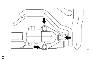
Tighten the 3 bolts in the order shown in the illustration in several steps.
- Torque:
- 5.0 N*m { 51 kgf*cm, 44 in.*lbf }
-
-
w/o Pin Top Plate:
-
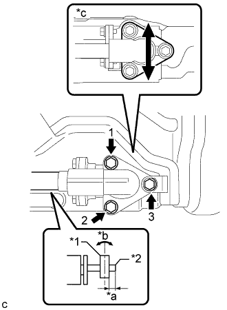
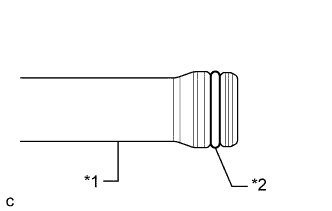
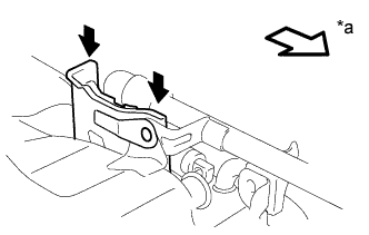
Text in Illustration *1 Hook *2 Valve Pin *a 3.5 to 6.5 mm (0.138 to 0.256 in.) *b Perpendicular *c Adjust the installation position Position the exhaust pipe gas control actuator subassembly so that 3.5 to 6.5 mm of the valve pin is protruding past the hook of the exhaust pipe gas control actuator sub-assembly.
-
Tighten the 3 bolts in the order shown in the illustration in several steps.
- Torque:
- 5.0 N*m { 51 kgf*cm, 44 in.*lbf }
-
Check that the hook of the exhaust pipe gas control actuator sub-assembly is at a point 3.5 to 6.5 mm from the end of the valve pin.
Tech Tips
-
If the hook is not installed within the specified range, loosen the 3 bolts of the exhaust pipe gas control actuator sub-assembly and 2 bolts of the exhaust by-pass pipe, then perform the steps from "Temporarily install the 3 bolts several threads".
-
If installation within the specified range cannot be obtained, replace the front exhaust pipe assembly.
-
-
-
Adjust the installation position of the exhaust by-pass pipe.
-
Loosen the 2 bolts slightly.
Note
Do not remove these 2 bolts.
-
Move the exhaust by-pass pipe up and down to properly settle the O-ring.
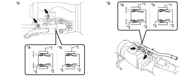
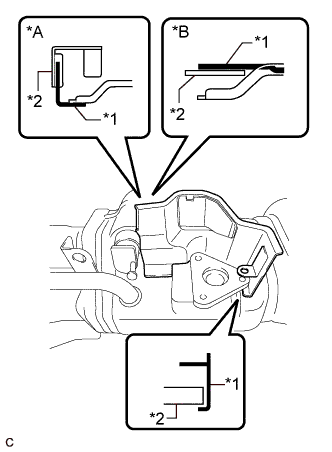
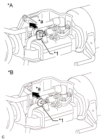
Text in Illustration *A w/ Pin Top Plate *B w/o Pin Top Plate *1 Exhaust Pipe Gas Control Actuator Sub-assembly *2 O-ring *3 Exhaust By-pass Pipe - - *a OK (O-ring is not deformed.) *b NG (O-ring is deformed.) Note
-
If this step is not performed, a coolant leak will develop.
-
Make sure to settle the O-ring to distribute the pressure applied to the upper part of the O-ring. Failure to do so may cause engine coolant to leak.
-
-
-
w/ Pin Top Plate:
-
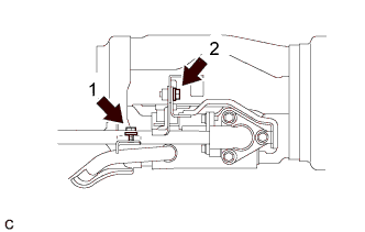
Tighten the 2 bolts in the order shown in the illustration.
- Torque:
- 8.5 N*m { 87 kgf*cm, 75 in.*lbf }
-
-
w/o Pin Top Plate:
-
While holding down the No. 2 exhaust pipe heat insulator and exhaust pipe plate, fully tighten the 2 bolts in the order shown in the illustration.
- Torque:
- 8.5 N*m { 87 kgf*cm, 75 in.*lbf }
-
-
When replacing the exhaust pipe gas control actuator sub-assembly with a new one:
-
Remove the spacer from the new exhaust pipe gas control actuator sub-assembly.
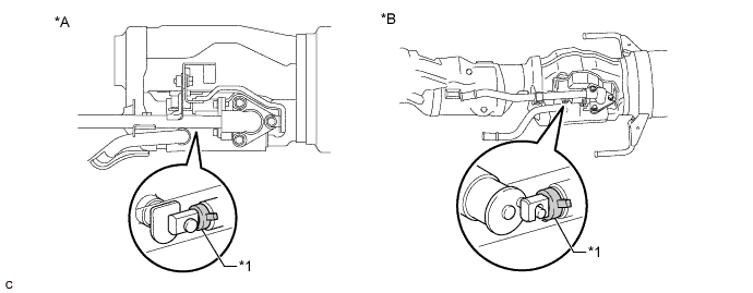
Text in Illustration *A w/ Pin Top Plate *B w/o Pin Top Plate *1 Spacer - - Note
To prevent a malfunction of the exhaust pipe gas control actuator sub-assembly, the spacer must be removed.
Tech Tips
The spacer is provided with a new exhaust pipe gas control actuator sub-assembly.
-
-
-
INSTALL FRONT EXHAUST PIPE ASSEMBLY
-
ADD COOLANT (for Engine)
-
Tighten the radiator drain cock plug.
-
Text in Illustration *1 B Line Add coolant to B line of the reserve tank.
Standard Capacity Item Capacity Engine coolant w/ Exhaust Heat Recirculation System:
6.9 liters (7.3 US qts, 6.1 lmp. qts)
w/o Exhaust Heat Recirculation System:
6.5 liters (6.9 US qts, 5.7 lmp. qts)
Tech Tips
TOYOTA vehicles are filled with TOYOTA SLLC at the factory. In order to avoid damage to the engine cooling system and other technical problems, only use TOYOTA SLLC or similar high quality ethylene glycol based non-silicate, non-amine, non-nitrite, non-borate coolant with long-life hybrid organic acid technology (coolant with long-life hybrid organic acid technology is a combination of low phosphates and organic acids).
Note
Never use water as a substitute for engine coolant.
-
Squeeze the radiator hoses several times by hand, and then check the level of the coolant.
If the coolant level is low, add coolant.
-
Put the engine in inspection mode Click here.
-
Install the reserve tank cap.
-
Bleed air from the cooling system.
Note
-
Before starting the engine, turn the A/C switch off.
-
Adjust the heater control to the maximum hot setting.
-
Adjust the blower speed to the low setting.
-
Warm up the engine until the thermostat opens. While the thermostat is open, allow the coolant to circulate for several minutes. (●1)
Tech Tips
The thermostat opening timing can be confirmed by squeezing the inlet radiator hose by hand, and sensing vibrations when the engine coolant starts to flow inside the hose.
CAUTION:
When squeezing the radiator hose:
-
Wear protective gloves.
-
Be careful as the radiator hoses are hot.
-
Keep your hands away from the radiator fans.
-
-
Stop the engine and wait until the coolant cools down. Then if the coolant level is below the low line, add coolant so that the level will be between the full and low lines. (●2)
-
Repeat the steps from (●1) to (●2) until the coolant level of the reserve tank remains above the low line.
-
-
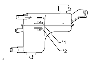
Text in Illustration *1 Full Line *2 Low Line After the engine has cooled down, check that the coolant level is between the full and low lines.
If the coolant level is low, add coolant to the full line on the reserve tank.
-
-
INSPECT FOR COOLANT LEAK (for Engine)
CAUTION:
Do not remove the reserve tank cap while the engine and radiator are still hot. Pressurized, hot engine coolant and steam may be released and cause serious burns.
Note
Before performing each inspection, turn the A/C switch off.
-
Remove the reserve tank cap.
-
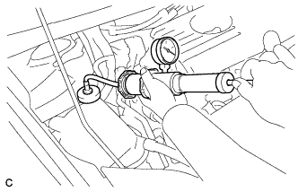
Fill the reserve tank with coolant, and then attach a radiator cap tester.
-
Put the engine in inspection mode Click here.
-
Warm up the engine.
-
Using a radiator cap tester, increase the pressure inside the radiator to 108 kPa (1.1 kgf/cm2, 16 psi), and check that the pressure does not drop. If the pressure drops, check the hoses, radiator, front exhaust pipe assembly, the heater hose around the engine coolant temperature sensor and engine water pump assembly for leaks. If no external leaks are found, check the heater core, cylinder block and cylinder head.
-
Remove the radiator cap tester.
-
Install the reserve tank cap.
-