FUEL INJECTOR REMOVAL
-
PRECAUTION
Note
After turning the power switch off, waiting time may be required before disconnecting the cable from the negative (-) auxiliary battery terminal. Therefore, make sure to read the disconnecting the cable from the negative (-) auxiliary battery terminal notice before proceeding with work Click here.
-
DISCHARGE FUEL SYSTEM PRESSURE
-
REMOVE REAR NO. 2 FLOOR BOARD
-
Remove the rear No. 2 floor board.
-
-
REMOVE REAR DECK FLOOR BOX
-
Remove the rear deck floor box.
-
-
REMOVE REAR NO. 3 FLOOR BOARD
-
Remove the rear No. 3 floor board.
-
-
REMOVE DECK FLOOR BOX RH
-
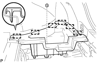
Remove the clip.
-
Disengage the 6 guides and remove the deck floor box RH.
-
-
REMOVE REAR FLOOR BOARD UPPER NO. 3 PLATE
-
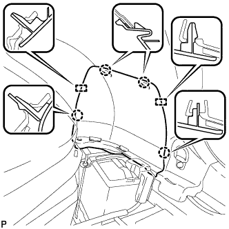
Disengage the 4 claws and 2 guides, and remove the rear floor board upper No. 3 plate.
-
-
DISCONNECT CABLE FROM NEGATIVE AUXILIARY BATTERY TERMINAL
Note
When disconnecting the cable, some systems need to be initialized after the cable is reconnected Click here.
-
REMOVE RADIATOR SUPPORT OPENING COVER
-

Remove the 9 clips and radiator support opening cover (for 9 Clip Type).
-
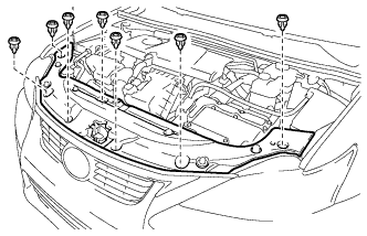
Remove the 7 clips and radiator support opening cover (for 7 Clip Type).
-
-
REMOVE NO. 2 CYLINDER HEAD COVER
-
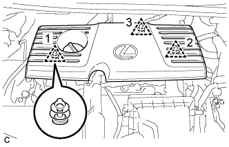
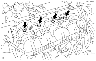
Remove the 3 clips and No. 2 cylinder head cover.
Note
-
Disengage the clips in the order shown in the illustration.
-
When disengaging clip 3, hold the end of the cover behind clip 3 and lift the cover straight up.
-
Attempting to disengage both front and rear clips at the same time may cause the cover to break.
-
Pull the cover straight up to remove. Attempting to pull the cover forward or pull it up by holding the left and right ends may cause the cover to break.
-
-
-
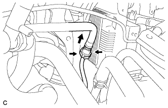
REMOVE AIR CLEANER CAP SUB-ASSEMBLY
-
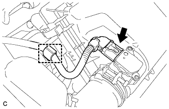
Disconnect the connector and wire harness clamp.
-
Disconnect the water hose from the clamp.
-
Disengage the 2 clamps and remove the air cleaner cap sub-assembly.
-
Loosen the hose clamp and disconnect the air cleaner hose assembly.
-
-
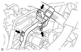
REMOVE INLET AIR CLEANER ASSEMBLY
-
Separate the water hose from the hose clamp.
-
Separate the wire harness clamp from the inlet air cleaner assembly.
-
Remove the 2 bolts, 2 clips and inlet air cleaner assembly.
-
-
REMOVE AIR CLEANER CASE
-
Remove the air cleaner filter element sub-assembly from the air cleaner case.
-
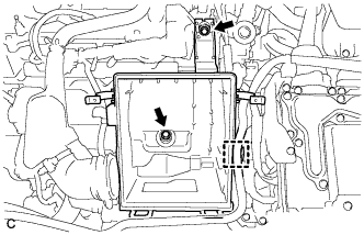
Disconnect the water hose from the clamp.
-
Remove the 2 bolts and air cleaner case.
-
-
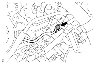
REMOVE AIR CLEANER HOSE ASSEMBLY
-
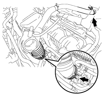
Disconnect the ventilation hose from the cylinder head cover sub-assembly.
-
Loosen the hose clamp and remove the air cleaner hose assembly from the throttle body assembly.
-
-
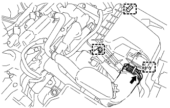
DISCONNECT ENGINE WIRE
-
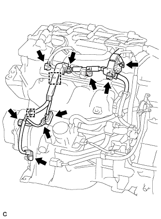
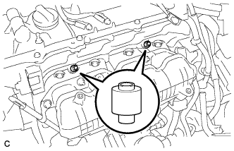
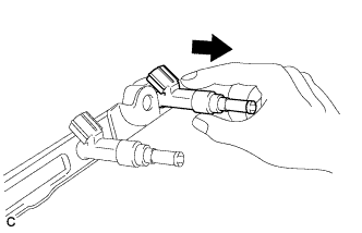
Disconnect the 4 fuel injector connectors.
-
Disconnect the 4 connectors.
-
Remove the bolt.
-
Disengage the 2 clamps to disconnect the wire harness.
-
-
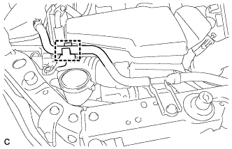
DISCONNECT FUEL TUBE SUB-ASSEMBLY
-
Release the claw and remove the No. 1 fuel pipe clamp.
-
Pinch the retainer of the fuel tube connector, and then pull the fuel tube connector off of the fuel pipe.
Note
-
Check for foreign matter in the fuel pipe around the fuel tube connector. Clean it if necessary. Foreign matter can affect the ability of the O-ring to seal the fuel tube connector and fuel pipe.
-
Do not use any tools to separate the fuel tube connector and fuel pipe.
-
Do not forcefully bend, kink or twist the fuel tube.
-
Keep the fuel tube connector and fuel pipe free from foreign matter.
-
If the fuel tube connector and fuel pipe are stuck together, pinch the fuel tube connector and turn it carefully to disconnect it.
-
Put the fuel tube connector and fuel pipe in plastic bags to prevent damage and contamination.
-
-
-
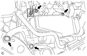
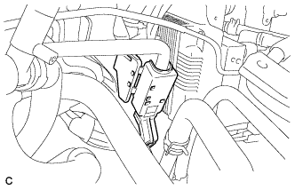
SEPARATE WATER BY-PASS PIPE
-
Disengage the clamp to disconnect the wire harness.
-
Remove the 2 bolts and nut, and separate the water by-pass pipe.
-
-
REMOVE FUEL DELIVERY PIPE SUB-ASSEMBLY
-
Remove the bolt.
-
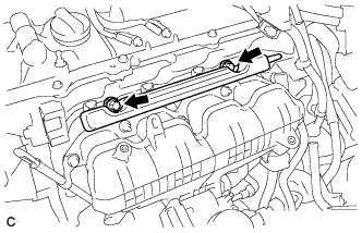
Remove the 2 bolts and fuel delivery pipe sub-assembly.
Note
Be careful not to drop the fuel injectors when removing the fuel delivery pipe.
-
-
REMOVE NO. 1 DELIVERY PIPE SPACER
-
Remove the 2 delivery pipe spacers from the cylinder head.
-
-
REMOVE FUEL INJECTOR ASSEMBLY
-
Pull the 4 fuel injector assemblies out of the fuel delivery pipe sub-assembly.
-
Remove the O-ring from each fuel injector assembly.
-
For reinstallation, attach a tag or label to each injector shaft.
Note
Prevent entry of foreign objects by covering the fuel injectors with plastic bags.
-
Remove the 4 injector vibration insulators.
-