- Click here
REMOVE OIL FILLER CAP SUB-ASSEMBLY
-
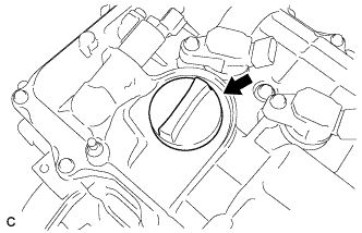
Remove the oil filler cap.
-
- Click here
REMOVE OIL FILLER CAP GASKET
-
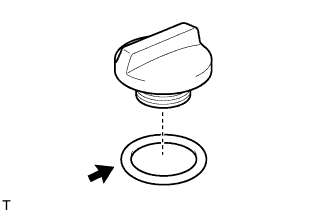
Remove the oil filler cap gasket.
-
- Click here
REMOVE ENGINE COVER JOINT BOLT
-
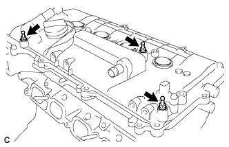
Remove the 3 engine cover joint bolts.
-
- Click here
REMOVE WIRING HARNESS CLAMP BRACKET
-
Remove the bolt and wiring harness clamp bracket.
-
- Click here
REMOVE SPARK PLUG
-
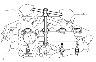
Using a 14 mm spark plug wrench, remove the 4 spark plugs.
-
- Click here
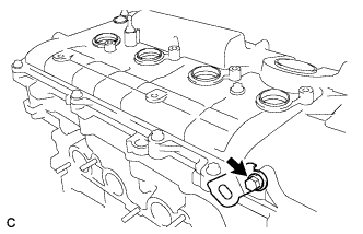
REMOVE CAMSHAFT POSITION SENSOR
-
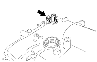
Remove the bolt and camshaft position sensor.
-
- Click here
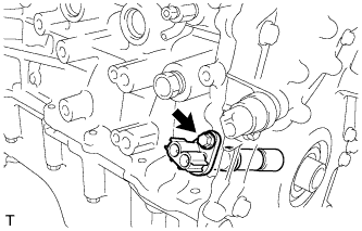
REMOVE CAMSHAFT TIMING OIL CONTROL VALVE ASSEMBLY
-
Remove the bolt and camshaft timing oil control valve.
-
Remove the O-ring from the camshaft timing oil control valve.
-
- Click here
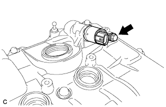
REMOVE CRANKSHAFT POSITION SENSOR
-
Remove the bolt and crankshaft position sensor.
-
- Click here
REMOVE ENGINE OIL PRESSURE SWITCH ASSEMBLY
-
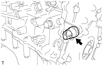
Using a 24 mm deep socket wrench, remove the engine oil pressure switch assembly.
-
- Click here
REMOVE KNOCK SENSOR
-
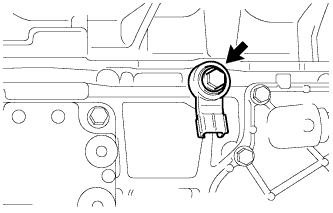
Remove the bolt and knock sensor.
-
- Click here
REMOVE ENGINE COOLANT TEMPERATURE SENSOR
-
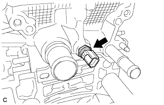
Remove the engine coolant temperature sensor and gasket.
-
- Click here
REMOVE CYLINDER HEAD COVER SUB-ASSEMBLY
-
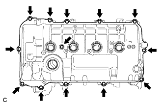
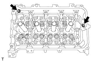
Remove the 13 bolts, seal washer and cylinder head cover.
Note:As the gaskets may stick to the cylinder head cover, be careful not to drop any of the gaskets into the engine when removing the cylinder head cover.
-
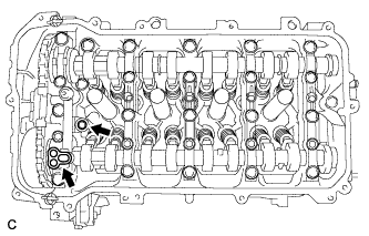
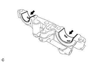
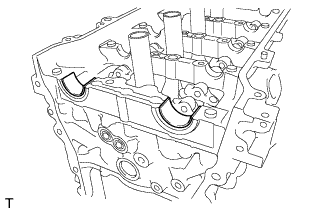
Remove the 2 gaskets from the camshaft bearing cap.
-
- Click here
REMOVE CYLINDER HEAD COVER GASKET
-
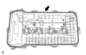
Remove the cylinder head cover gasket.
-
- Click here
REMOVE SPARK PLUG TUBE GASKET
-
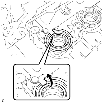
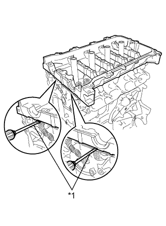
Pry up the 4 claws of the ventilation baffle plate.
Note:Do not deform the claws of the baffle plate more than necessary.
-
Remove the 4 gaskets from the cylinder head cover.
Tip:Prevent the plug tube gaskets from being deformed as much as possible. The removed gaskets will be used when installing new gaskets.
Note:Be careful not to damage the cylinder head cover.
-
- Click here
REMOVE OIL FILTER CAP ASSEMBLY
-
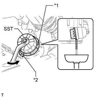
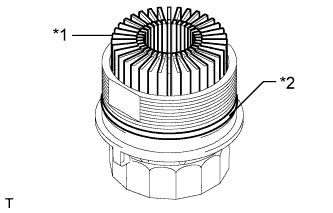
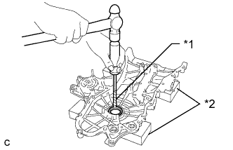
Using SST, loosen the oil filter cap 4 revolutions, align the cap ribs vertically, and drain the remaining engine oil in the oil filter cap.
Table 1. Text in Illustration *1 Cap Rib *2 Oil Filter Bracket Clip 09228-06501 Note:Do not remove the oil filter bracket clip when removing the oil filter cap assembly.
Tip:Set a container below the oil filter cap assembly before loosening the oil filter cap.
-
Remove the oil filter cap assembly.
-
Remove the oil filter element and O-ring from the oil filter cap.
Table 2. Text in Illustration *1 Oil Filter Element *2 O-ring Note:Be sure to remove the O-ring (for the cap) by hand, without using any tools, to prevent damage to the groove for the O-ring on the cap.
-
- Click here
REMOVE INLET WATER SUB-ASSEMBLY
-
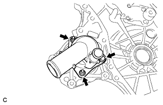
Remove the bolt, 2 nuts, inlet water sub-assembly and gasket.
-
- Click here
REMOVE INLET WATER SUB-ASSEMBLY STUD BOLT
Note:If a stud bolt is deformed or its threads are damaged, replace it.
- Click here
SET NO. 1 CYLINDER TO TDC/COMPRESSION
-
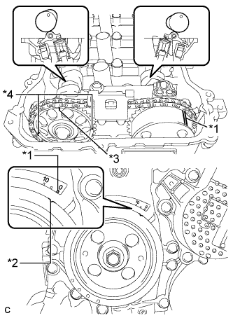
Turn the crankshaft pulley until its notch and timing mark "0" of the timing chain cover are aligned.
Table 3. Text in Illustration *1 Timing Mark *2 Timing Notch *3 Timing Mark (Rectangle) *4 Mark (Circle) Tip:There are 3 marks on the camshaft timing sprocket. Make sure that the timing mark (rectangle) is at the top.
-
Check that the timing marks on both the camshaft timing sprocket and the camshaft timing gear are facing upward as shown in the illustration.
If not, turn the crankshaft 1 complete revolution (360°) and align the marks as above.
-
- Click here
REMOVE CRANKSHAFT PULLEY
-
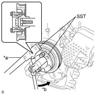
Using SST, hold the pulley in place and loosen the pulley bolt.
Table 4. Text in Illustration *a Hold *b Turn 09213-58014 91551-80840 09330-00021 -
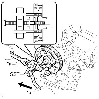
Using SST, remove the crankshaft pulley and pulley bolt.
Table 5. Text in Illustration *a Hold *b Turn 09950-50013 09951-05010 09952-05010 09953-05020 09954-05021
-
- Click here
REMOVE NO. 1 CHAIN TENSIONER ASSEMBLY
-
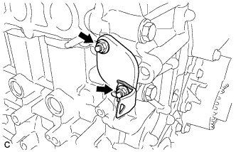
Remove the 2 nuts, bracket, chain tensioner and gasket.
Note:Do not turn the crankshaft without the No. 1 chain tensioner installed.
-
- Click here
REMOVE TIMING CHAIN COVER SUB-ASSEMBLY
-
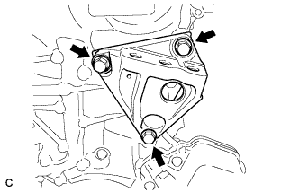
Remove the 3 bolts and engine mounting bracket RH.
-
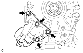
Remove the 4 bolts and oil filter bracket.
-
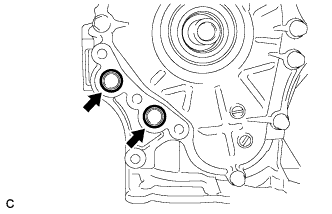
Remove the 2 O-rings.
-
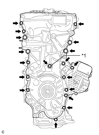
Remove the 18 bolts and seal washer.
Table 6. Text in Illustration *1 Seal Washer -
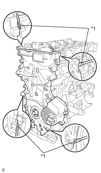
Remove the timing chain cover by prying between the timing chain cover and cylinder head or cylinder block with a screwdriver.
Table 7. Text in Illustration *1 Protective Tape Note:
-
Be careful not to damage the contact surfaces of the timing chain cover, cylinder block, and cylinder head.
-
Pry the timing chain cover out evenly in order to prevent damaging the knock pins.
Tip:Tape the screwdriver tip before use.
-
-
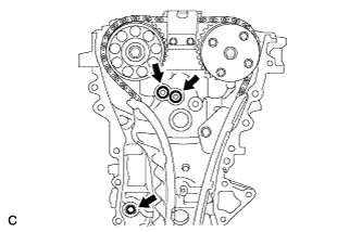
Remove the 3 O-rings.
-
- Click here
REMOVE TIMING CHAIN COVER OIL SEAL
-
Place the timing chain cover on wooden blocks.
-
Using a screwdriver and hammer, knock out the oil seal.
Table 8. Text in Illustration *1 Protective Tape *2 Wooden Block Tip:Tape the screwdriver tip before use.
Note:Do not damage the surface of the oil seal press fit hole.
-
- Click here
REMOVE CHAIN TENSIONER SLIPPER
-
Remove the chain tensioner slipper from the cylinder block.
-
- Click here
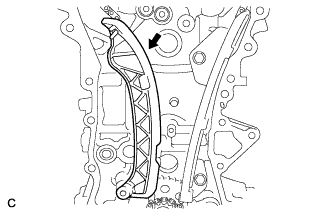
REMOVE NO. 1 CHAIN VIBRATION DAMPER
-
Remove the 2 bolts and chain vibration damper.
-
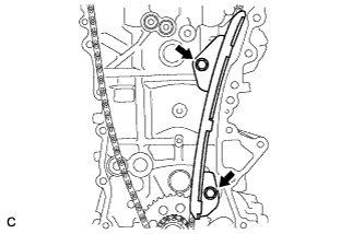
- Click here
REMOVE NO. 2 CHAIN VIBRATION DAMPER
-
Remove the 2 bolts and No. 2 chain vibration damper.
-
- Click here
REMOVE CHAIN SUB-ASSEMBLY
-
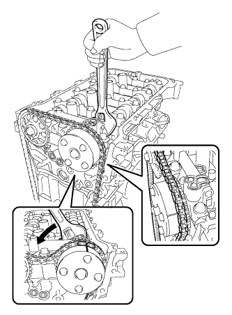
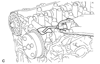
Hold the hexagonal portion of the camshaft with a wrench and turn the camshaft timing gear counterclockwise to loosen the chain between the camshaft timing gears.
-
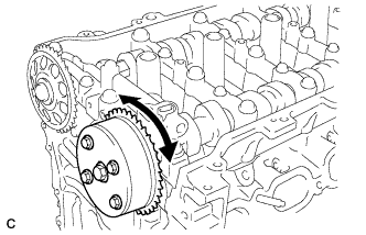
With the chain loosened, release the chain from the camshaft timing gear and place it on the camshaft timing gear.
Tip:Be sure to release the chain from the sprocket completely.
-
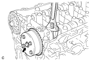
Turn the camshaft clockwise to return it to the original position and remove the chain.
-
- Click here
REMOVE CRANKSHAFT TIMING SPROCKET
-
Remove the crankshaft timing sprocket.
-
- Click here
REMOVE NO. 2 CHAIN SUB-ASSEMBLY
-
Temporarily tighten the crankshaft pulley and crankshaft pulley bolt.
-
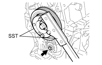
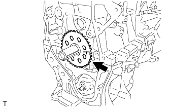
Using SST, remove the oil pump drive shaft sprocket nut while holding the crankshaft pulley.
09213-58014 91551-80840 09330-00021 -
Remove SST, the crankshaft pulley and crankshaft pulley bolt.
-
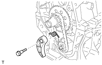
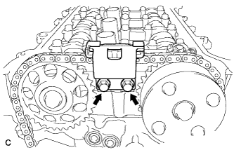
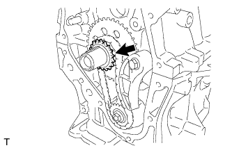
Remove the bolt, chain tensioner plate and chain damper spring.
-
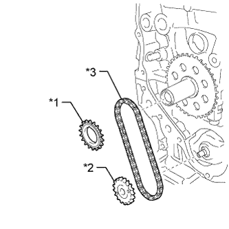
Remove the oil pump drive gear, oil pump drive shaft gear and No. 2 chain sub-assembly.
Table 9. Text in Illustration *1 Oil Pump Drive Gear *2 Oil Pump Drive Shaft Gear *3 No. 2 Chain Sub-assembly
-
- Click here
REMOVE NO. 1 CRANKSHAFT POSITION SENSOR PLATE
-
Remove the crankshaft position sensor plate.
-
- Click here
REMOVE CRANKSHAFT TIMING GEAR KEY
-
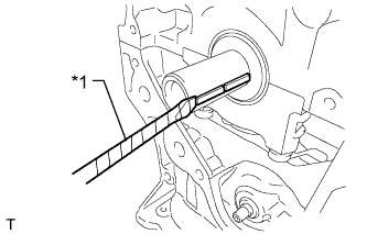
Using a screwdriver, remove the 2 crankshaft timing gear keys.
Table 10. Text in Illustration *1 Protective Tape Tip:Tape the screwdriver tip before use.
-
- Click here
INSPECT CAMSHAFT TIMING GEAR ASSEMBLY
-
Inspect the lock of the camshaft timing gear.
-
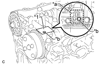
After cleaning and degreasing the VVT oil hole on the intake side of the No. 1 camshaft bearing cap, completely seal the oil hole with adhesive tape or equivalent as shown in the illustration to prevent air from leaking.
Table 11. Text in Illustration *1 Adhesive Tape *a Adhesive Tape Sealing Area *b Prick a Hole Note:Be sure to cover the oil hole completely because air leaks due to insufficient sealing will prevent the lock pin from being released.
-
Prick a hole in the tape covering the oil hole as shown in the illustration. (Procedure A)
-
Apply approximately 150 kPa (1.5 kgf/cm2, 22 psi) of air pressure to the hole pricked in procedure A to release the lock pin.
Note:
-
If air leaks out, reattach the adhesive tape.
-
Cover the oil hole with a piece of cloth when applying air pressure to prevent oil from spraying.
-
-
Forcibly turn the camshaft timing gear in the advance direction (counterclockwise).
Tip:Depending on the air pressure applied, the camshaft timing gear may turn in the advance direction without assistance.
-
Turn the camshaft timing gear within its movable range (26.5 to 28.5°) 2 or 3 times without turning it to the most retarded position. Make sure that the camshaft timing gear turns smoothly.
-
Remove the adhesive tape from the No. 1 camshaft bearing cap.
-
- Click here
REMOVE CAMSHAFT TIMING GEAR ASSEMBLY
-
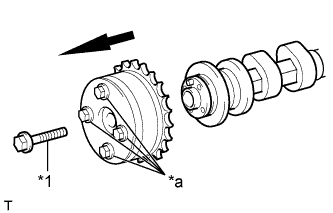
Remove the flange bolt while holding the hexagonal portion of the camshaft with a wrench, and then remove the camshaft timing gear.
Table 12. Text in Illustration *1 Flange Bolt *a Do not remove Note:
-
Before removing the camshaft timing gear, make sure that the lock pin has been released.
-
Be sure not to remove the other 4 bolts.
-
Keep the camshaft timing gear horizontal while removing it from the camshaft.
-
-
- Click here
REMOVE CAMSHAFT TIMING SPROCKET
-
Remove the flange bolt while holding the hexagonal portion of the camshaft with a wrench, and then remove the camshaft timing gear.
Table 13. Text in Illustration *1 Flange Bolt *a Do not remove Note:
-
Before removing the camshaft timing gear, make sure that the lock pin has been released.
-
Be sure not to remove the other 4 bolts.
-
Keep the camshaft timing gear horizontal while removing it from the camshaft.
-
-
- Click here
REMOVE CAMSHAFT BEARING CAP
-
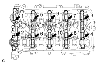
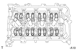
Uniformly loosen and remove the 10 bearing cap bolts in the sequence shown in the illustration.
-
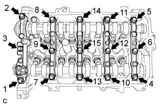
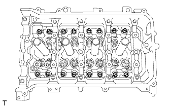
Uniformly loosen and remove the 15 bearing cap bolts in the sequence shown in the illustration.
Note:Uniformly loosen the bearing cap bolts while keeping the camshaft housing level.
-
Remove the 5 bearing caps.
Tip:Arrange the removed parts in the correct order.
-
- Click here
REMOVE CAMSHAFT
-
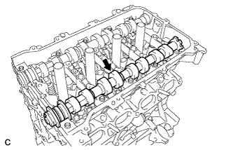
Remove the camshaft.
-
- Click here
REMOVE NO. 2 CAMSHAFT
-
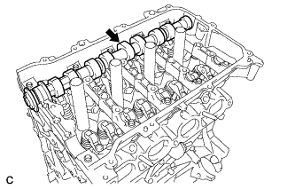
Remove the No. 2 camshaft.
-
- Click here
REMOVE CAMSHAFT HOUSING STRAIGHT PIN
Note:It is not necessary to remove a straight pin unless it is being replaced.
- Click here
REMOVE NO. 1 VALVE ROCKER ARM SUB-ASSEMBLY
-
Remove the 16 valve rocker arms.
Tip:Arrange the removed parts in the correct order.
-
- Click here
REMOVE VALVE LASH ADJUSTER ASSEMBLY
-
Remove the 16 valve lash adjusters from the cylinder head.
Tip:Arrange the removed parts in the correct order.
-
- Click here
REMOVE VALVE STEM CAP
-
Remove the 16 valve stem caps.
Tip:Arrange the removed parts in the correct order.
-
- Click here
REMOVE OIL CONTROL VALVE FILTER
-
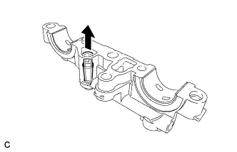
Remove the oil control valve filter from the No. 1 camshaft bearing cap.
-
- Click here
REMOVE NO. 1 CAMSHAFT BEARING
-
Remove the 2 camshaft bearings.
-
- Click here
REMOVE NO. 2 CAMSHAFT BEARING
-
Remove the 2 camshaft bearings.
-
- Click here
REMOVE CAMSHAFT HOUSING SUB-ASSEMBLY
-
Remove the 2 bolts.
-
Remove the camshaft housing by prying between the cylinder head and camshaft housing with a screwdriver.
Table 14. Text in Illustration *1 Protective Tape Note:Be careful not to damage the contact surfaces of the cylinder head and camshaft housing.
Tip:Tape the screwdriver tip before use.
-
- Click here
REMOVE CYLINDER HEAD SUB-ASSEMBLY
-
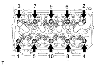
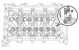
Using a 10 mm bi-hexagon wrench, uniformly loosen and remove the 10 cylinder head bolts and 10 plate washers in several steps in the sequence shown in the illustration.
Note:
-
Be careful not to drop washers into the cylinder head.
-
Head warpage or cracking could result from removing the bolts in the wrong order.
-
-
Using a screwdriver with its tip wrapped with tape, pry between the cylinder head and cylinder block, and remove the cylinder head.
Note:Be careful not to damage the contact surfaces of the cylinder head and cylinder block.
-
- Click here
REMOVE CYLINDER HEAD GASKET
-
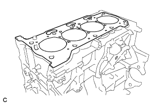
Remove the cylinder head gasket.
-
- Click here
REMOVE VENTILATION VALVE SUB-ASSEMBLY
-
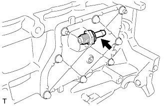
Remove the ventilation valve sub-assembly.
-
- Click here
REMOVE OIL PAN DRAIN PLUG
-
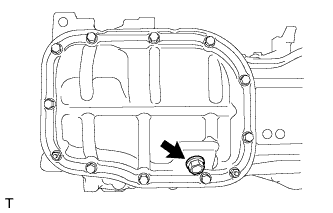
Remove the drain plug and gasket.
-
- Click here
REMOVE NO. 2 OIL PAN SUB-ASSEMBLY
-
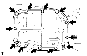
Remove the 10 bolts and 2 nuts.
-
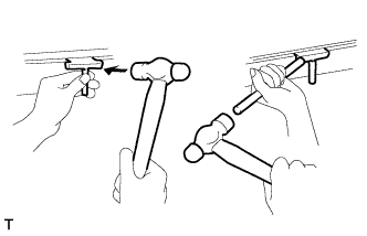
Insert the blade of an oil pan seal cutter between the crankcase and oil pan. Cut through the sealer and remove the oil pan.
Note:Be careful not to damage the contact surfaces of the crankcase, chain cover and oil pan.
-
- Click here
REMOVE OIL PUMP ASSEMBLY
-
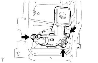
Remove the 3 bolts and oil pump.
-
- Click here
REMOVE STIFFENING CRANKCASE ASSEMBLY
-
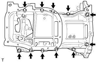
Uniformly loosen and remove the 11 bolts.
-
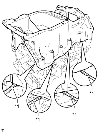
Using a screwdriver, remove the stiffening crankcase by prying between the stiffening crankcase and cylinder block.
Table 15. Text in Illustration *1 Protective Tape Tip:Tape the screwdriver tip before use.
Note:Be careful not to damage the contact surfaces of the crankcase and cylinder block.
-
- Click here
REMOVE NO. 1 TAPER SCREW PLUG
-
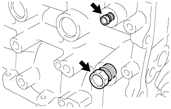
Remove the 2 No. 1 taper screw plugs.
-
- Click here
REMOVE STIFFENING CRANKCASE STUD BOLT
Note:If a stud bolt is deformed or its threads are damaged, replace it.
- Click here
REMOVE STIFFENING CRANKCASE RING PIN
Note:It is not necessary to remove a ring pin unless it is being replaced.
- Click here
REMOVE ENGINE REAR OIL SEAL
-
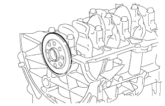
Remove the engine rear oil seal from the cylinder block.
-