CAMSHAFT REMOVAL

-
REMOVE ENGINE ASSEMBLY WITH TRANSAXLE
-
INSTALL ENGINE STAND
-
Install the engine onto an engine stand with the bolts.
-
-
REMOVE ENGINE HANGERS
-
Remove the 2 bolts and No. 1 and No. 2 engine hangers.
-
-
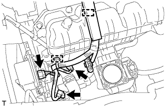
REMOVE THROTTLE BODY ASSEMBLY
-
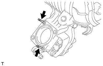
Type A:
-
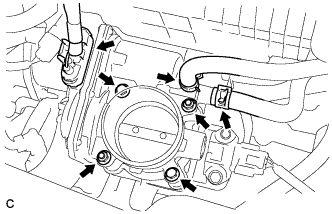
Disconnect the connector.
-
Disconnect the No. 1 water by-pass hose and No. 2 water by-pass hose.
-
Remove the 2 bolts, 2 nuts and throttle body assembly.
-
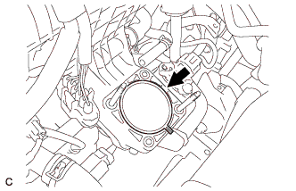
Remove the gasket from the intake manifold.
-
-
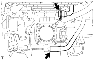
Type B:
-

Disconnect the connector.
-
Disconnect the No. 1 water by-pass hose and No. 2 water by-pass hose.
-
Remove the 4 bolts and throttle body assembly.
-
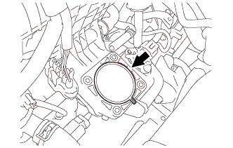
Remove the gasket from the intake manifold.
-
-
-
REMOVE ENGINE OIL LEVEL DIPSTICK GUIDE
-
Remove the engine oil level dipstick.
-
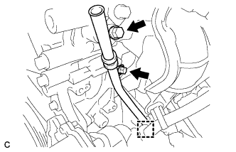
Remove the 2 bolts, clamp and engine oil level dipstick guide.
-
Remove the O-ring from the engine oil level dipstick guide.
-
-
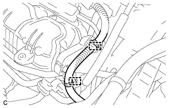
REMOVE EGR PIPE ASSEMBLY (w/ EGR System)
-
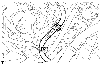
Disconnect the 2 wire harness clamps.
-
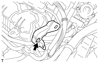
Remove the bolt and wire harness support.
-
Remove the 4 bolts, EGR pipe assembly and 2 gaskets.
-
-
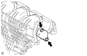
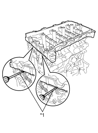
REMOVE EGR VALVE ASSEMBLY (w/ EGR System)
-
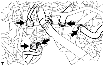
Disconnect the connector, wire harness clamp and 4 water hoses.
-
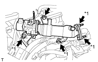
Text in Illustration *1 Stud Bolt and Nut Remove the 4 nuts and bolt.
-
Using an E8 "TORX" socket wrench, remove the 4 stud bolts and EGR valve with cooler assembly.
-
Remove the gasket.
-
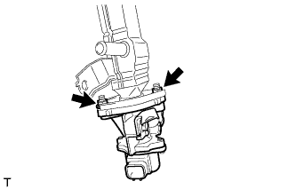
Remove the 2 nuts, EGR valve assembly and gasket.
-
-
REMOVE EGR WITH COOLER PIPE SUB-ASSEMBLY (w/ EGR System)
-
Disconnect the connector, wire harness clamp and 4 water hoses.
-
Text in Illustration *1 Stud Bolt and Nut Remove the 4 nuts and bolt.
-
Using an E8 "TORX" socket wrench, remove the 4 stud bolts and EGR valve with cooler assembly.
-
Remove the gasket.
-
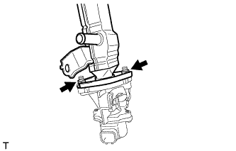
Remove the 2 nuts, EGR cooler sub-assembly and gasket.
-
-
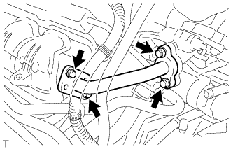
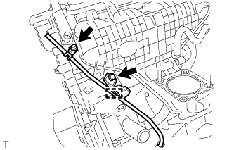
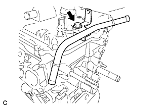
REMOVE WATER BY-PASS PIPE (w/o EGR System)
-
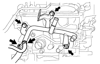
Disconnect the 2 water by-pass hoses.
-
Remove the 2 bolts, nut and water by-pass pipe.
-
-
REMOVE INTAKE MANIFOLD
-
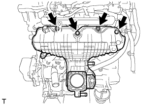
w/o EGR System:
-
Disconnect the 2 wire harness clamps from the wire harness support.
-

Remove the bolt and wire harness support from the surge tank cover.
-
Remove the 2 bolts and surge tank cover from the intake manifold.
-
Remove the gasket from the intake manifold.
-
-
Disconnect the 3 connectors and 2 wire harness clamps.
-
Remove the engine oil level dipstick.
-
Disconnect the wire harness clamp, and then remove the 2 bolts and engine oil level dipstick guide sub-assembly.
-
Remove the O-ring from the engine oil level dipstick guide sub-assembly.
-
Disconnect the fuel vapor feed hose and ventilation hose from the intake manifold.
-
Remove the 2 bolts, 2 nuts and intake manifold.
-
Remove the No. 1 intake manifold to head gasket from the intake manifold.
-
w/ Stud Bolt:
-
Using an E6 "TORX" socket wrench, remove the 2 stud bolts from the intake manifold.
Tech Tips
If a stud bolt is deformed or the threads are damaged, replace the stud bolt.
-
-
-
REMOVE FUEL VAPOR FEED PIPE
-
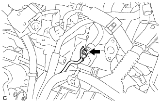
Remove the bolt and fuel vapor feed pipe.
-
-
REMOVE FUEL DELIVERY PIPE SUB-ASSEMBLY
-
Remove the bolt.
-
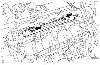
Remove the 2 bolts and fuel delivery pipe sub-assembly with the 4 fuel injector assemblies.
Note
Be careful not to drop the fuel injector assemblies when removing the fuel delivery pipe sub-assembly.
-
-
REMOVE NO. 1 DELIVERY PIPE SPACER
-
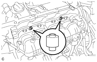
Remove the 2 No. 1 delivery pipe spacers from the cylinder head.
-
-
REMOVE FUEL INJECTOR ASSEMBLY
-
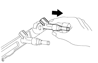
Pull the 4 fuel injector assemblies out of the fuel delivery pipe sub-assembly.
-
Remove the O-ring from each fuel injector assembly.
-
For reinstallation, attach a tag or label with the corresponding cylinder number to each fuel injector shaft.
Note
Protect the fuel injector assemblies by covering them with plastic bags.
-
Remove the 4 injector vibration insulators.
-
-
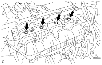
REMOVE IGNITION COIL ASSEMBLY
-
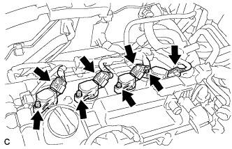
Disconnect the 4 ignition coil connectors.
-
Remove the 4 bolts and 4 ignition coils.
Note
When removing each ignition coil, do not damage the plug cap on the engine head cover opening or the upper edge of the spark plug tube.
-
-
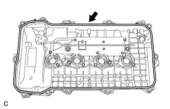
REMOVE CYLINDER HEAD COVER SUB-ASSEMBLY
-
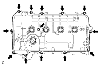
Remove the 13 bolts, seal washer and cylinder head cover.
Note
As the gaskets may stick to the cylinder head cover, be careful not to drop any of the gaskets into the engine when removing the cylinder head cover.
-
Remove the 2 gaskets from the camshaft bearing cap.
-
-
REMOVE CYLINDER HEAD COVER GASKET
-
Remove the cylinder head cover gasket.
-
-
REMOVE SPARK PLUG TUBE GASKET
-
Pry up the 4 claws of the ventilation baffle plate.
Note
Do not deform the claws of the baffle plate more than necessary.
-
Remove the 4 gaskets from the cylinder head cover.
Tech Tips
Prevent the plug tube gaskets from being deformed as much as possible. The removed gaskets will be used when installing new gaskets.
Note
Be careful not to damage the cylinder head cover.
-
-
SET NO. 1 CYLINDER TO TDC/COMPRESSION
-
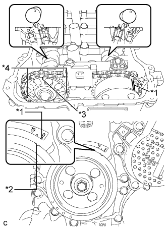
Text in Illustration *1 Timing Mark *2 Timing Notch *3 Timing Mark (Rectangle) *4 Mark (Circle) Turn the crankshaft pulley until its notch and timing mark "0" of the timing chain cover are aligned.
Tech Tips
There are 3 marks on the camshaft timing sprocket. Make sure that the timing mark (rectangle) is at the top.
-
Check that the timing marks on both the camshaft timing sprocket and the camshaft timing gear are facing upward as shown in the illustration.
If not, turn the crankshaft 1 complete revolution (360°) and align the marks as above.
-
-
REMOVE CRANKSHAFT PULLEY
-
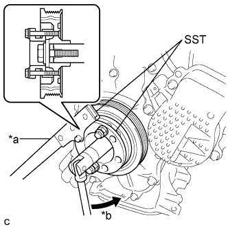
Text in Illustration *a Hold *b Turn Using SST, hold the pulley in place and loosen the pulley bolt.
- SST
- 09213-58014 ( 91551-80840 )
- 09330-00021
-
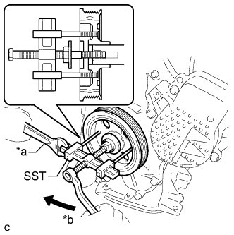
Text in Illustration *a Hold *b Turn Using SST, remove the crankshaft pulley and pulley bolt.
- SST
- 09950-50013 ( 09951-05010, 09952-05010, 09953-05020, 09954-05021 )
-
-
REMOVE NO. 1 CHAIN TENSIONER ASSEMBLY
-
Remove the 2 nuts, bracket, chain tensioner and gasket.
Note
Do not turn the crankshaft without the No. 1 chain tensioner installed.
-
-
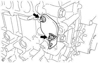
REMOVE TIMING CHAIN COVER SUB-ASSEMBLY
-
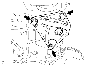
Remove the 3 bolts and engine mounting bracket RH.
-
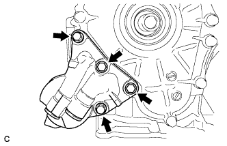
Remove the 4 bolts and oil filter bracket.
-
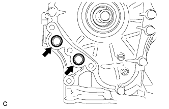
Remove the 2 O-rings.
-
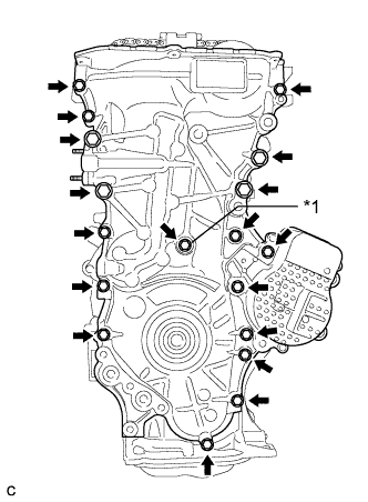
Text in Illustration *1 Seal Washer Remove the 18 bolts and seal washer.
-
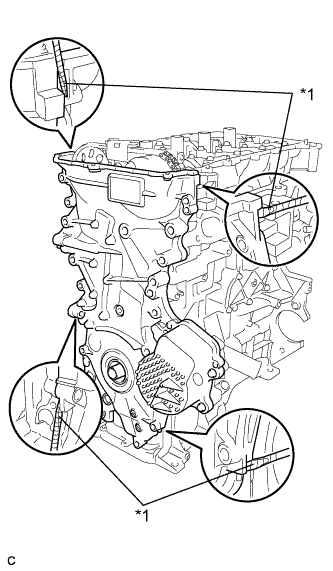
Text in Illustration *1 Protective Tape Remove the timing chain cover by prying between the timing chain cover and cylinder head or cylinder block with a screwdriver.
Note
-
Be careful not to damage the contact surfaces of the timing chain cover, cylinder block, and cylinder head.
-
Pry the timing chain cover out evenly in order to prevent damaging the knock pins.
Tech Tips
Tape the screwdriver tip before use.
-
-
Remove the 3 O-rings.
-
-
REMOVE TIMING CHAIN COVER OIL SEAL
-
Place the timing chain cover on wooden blocks.
-
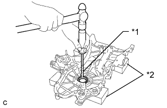
Text in Illustration *1 Protective Tape *2 Wooden Block Using a screwdriver and hammer, knock out the oil seal.
Tech Tips
Tape the screwdriver tip before use.
Note
Do not damage the surface of the oil seal press fit hole.
-
-
REMOVE CHAIN TENSIONER SLIPPER
-
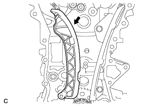
Remove the chain tensioner slipper from the cylinder block.
-
-
REMOVE NO. 1 CHAIN VIBRATION DAMPER
-
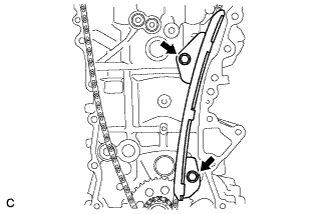
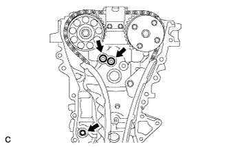
Remove the 2 bolts and chain vibration damper.
-
-
REMOVE NO. 2 CHAIN VIBRATION DAMPER
-
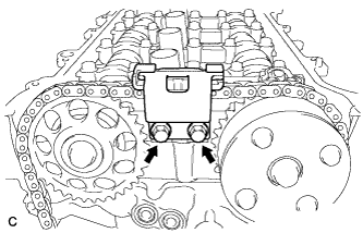
Remove the 2 bolts and No. 2 chain vibration damper.
-
-
REMOVE CHAIN SUB-ASSEMBLY
-
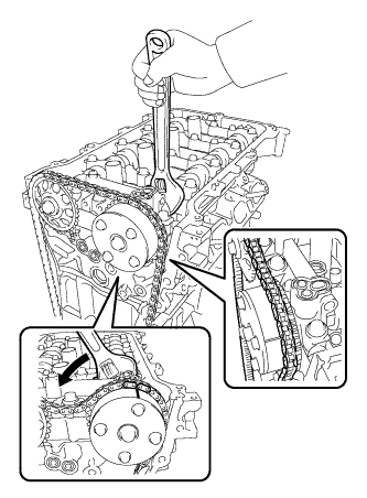
Hold the hexagonal portion of the camshaft with a wrench and turn the camshaft timing gear counterclockwise to loosen the chain between the camshaft timing gears.
-
With the chain loosened, release the chain from the camshaft timing gear and place it on the camshaft timing gear.
Tech Tips
Be sure to release the chain from the sprocket completely.
-
Turn the camshaft clockwise to return it to the original position and remove the chain.
-
-
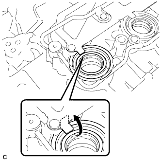
INSPECT CAMSHAFT TIMING GEAR ASSEMBLY
-
Inspect the lock of the camshaft timing gear.
-
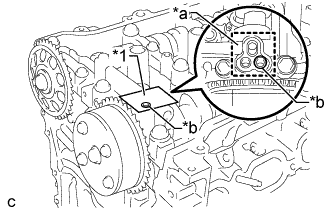
Text in Illustration *1 Adhesive Tape *a Adhesive Tape Sealing Area *b Prick a Hole After cleaning and degreasing the VVT oil hole on the intake side of the No. 1 camshaft bearing cap, completely seal the oil hole with adhesive tape or equivalent as shown in the illustration to prevent air from leaking.
Note
Be sure to cover the oil hole completely because air leaks due to insufficient sealing will prevent the lock pin from being released.
-
Prick a hole in the tape covering the oil hole as shown in the illustration. (Procedure A)
-
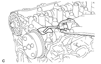
Apply approximately 150 kPa (1.5 kgf/cm2, 22 psi) of air pressure to the hole pricked in procedure A to release the lock pin.
Note
-
If air leaks out, reattach the adhesive tape.
-
Cover the oil hole with a piece of cloth when applying air pressure to prevent oil from spraying.
-
-
Forcibly turn the camshaft timing gear in the advance direction (counterclockwise).
Tech Tips
Depending on the air pressure applied, the camshaft timing gear may turn in the advance direction without assistance.
-
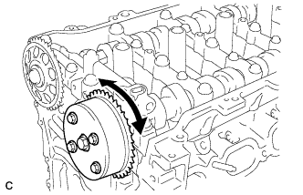
Turn the camshaft timing gear within its movable range (26.5 to 28.5°) 2 or 3 times without turning it to the most retarded position. Make sure that the camshaft timing gear turns smoothly.
-
Remove the adhesive tape from the No. 1 camshaft bearing cap.
-
-
REMOVE CAMSHAFT TIMING GEAR ASSEMBLY
-
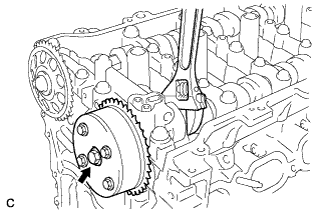
Text in Illustration *1 Flange Bolt *a Do not remove Remove the flange bolt while holding the hexagonal portion of the camshaft with a wrench, and then remove the camshaft timing gear.
Note
-
Before removing the camshaft timing gear, make sure that the lock pin has been released.
-
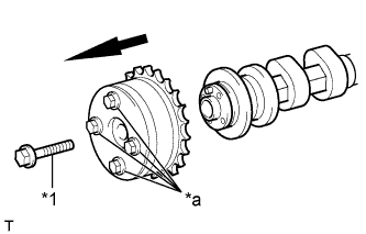
Be sure not to remove the other 4 bolts.
-
Keep the camshaft timing gear horizontal while removing it from the camshaft.
-
-
-
REMOVE CAMSHAFT TIMING SPROCKET
-
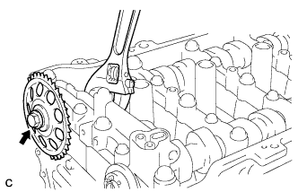
Remove the flange bolt while holding the hexagonal portion of the camshaft with a wrench, and then remove the camshaft timing sprocket.
-
-
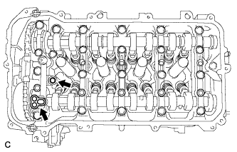
REMOVE CAMSHAFT BEARING CAP
-
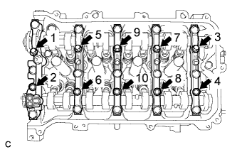
Uniformly loosen and remove the 10 bearing cap bolts in the sequence shown in the illustration.
-
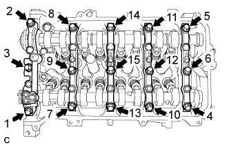
Uniformly loosen and remove the 15 bearing cap bolts in the sequence shown in the illustration.
Note
Uniformly loosen the bearing cap bolts while keeping the camshaft housing level.
-
Remove the 5 bearing caps.
Tech Tips
Arrange the removed parts in the correct order.
-
-
REMOVE CAMSHAFT
-
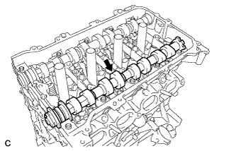
Remove the camshaft.
-
-
REMOVE NO. 2 CAMSHAFT
-
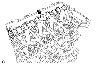
Remove the No. 2 camshaft.
-
-
REMOVE NO. 1 CAMSHAFT BEARING
-
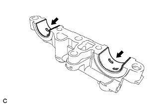
Remove the 2 No. 1 camshaft bearings.
-
-
REMOVE NO. 2 CAMSHAFT BEARING
-
Remove the 2 No. 2 camshaft bearings.
-
-
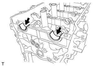
REMOVE CAMSHAFT HOUSING SUB-ASSEMBLY
-
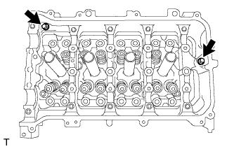
Remove the 2 bolts.
-
Text in Illustration *1 Protective Tape Remove the camshaft housing by prying between the cylinder head and camshaft housing with a screwdriver.
Note
Be careful not to damage the contact surfaces of the cylinder head and camshaft housing.
Tech Tips
Tape the screwdriver tip before use.
-