COMBINATION SWITCH INSPECTION
-
INSPECT COMBINATION SWITCH ASSEMBLY
-
Inspect EV switch
-
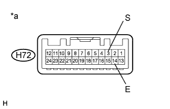
Text in Illustration *a Component without Harness Connected
(Combination Switch Assembly)
Measure the resistance according to the value(s) in the table below.
Standard Resistance Tester Connection Condition Specified Condition H72-3 (S) - H72-14 (E) EV switch being pushed and held Below 1 Ω EV switch not pushed 10 kΩ or higher If the result is not as specified, replace the combination switch assembly.
-
-
Inspect SPORT mode switch
-
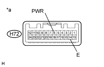
Text in Illustration *a Component without Harness Connected
(Combination Switch Assembly)
Measure the resistance according to the value(s) in the table below.
Standard Resistance Tester Connection Condition Specified Condition H72-6 (PWR) - H72-14 (E) Mode switch being turned and held at SPORT position Below 1 Ω Mode switch not turned 10 kΩ or higher If the result is not as specified, replace the combination switch assembly.
-
-
Inspect ECO mode switch
-
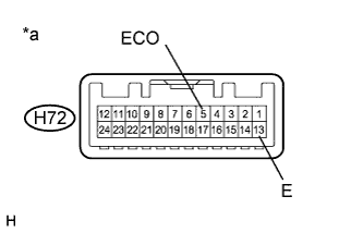
Text in Illustration *a Component without Harness Connected
(Combination Switch Assembly)
Measure the resistance according to the value(s) in the table below.
Standard Resistance Tester Connection Condition Specified Condition H72-5 (ECO) - H72-13 (E) Mode switch being turned and held at ECO position Below 1 Ω Mode switch not turned 10 kΩ or higher If the result is not as specified, replace the combination switch assembly.
-
-
Inspect NORMAL mode switch
-
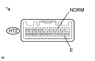
Text in Illustration *a Component without Harness Connected
(Combination Switch Assembly)
Measure the resistance according to the value(s) in the table below.
Standard Resistance Tester Connection Condition Specified Condition H72-4 (NORM) - H72-14 (E) Mode switch being pushed and held at NORMAL position Below 1 Ω Mode switch not pushed 10 kΩ or higher If the result is not as specified, replace the combination switch assembly.
-
-
Inspect illumination
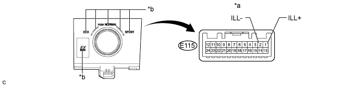
Text in Illustration *a Component without Harness Connected
(Combination Switch Assembly)
*b Integration Control and Panel Assembly Illumination
-
Apply battery voltage between the terminals of the switch, and check the illumination condition of the combination switch assembly.
Standard Measurement Condition Specified Condition Auxiliary battery positive (+) →Terminal E115-1 (ILL+)
Auxiliary battery negative (-) →Terminal E115-2 (ILL-)
illuminates If the result is not as specified, replace the integration control and panel assembly.
-
-
-
INSPECT POSITION INDICATOR HOUSING ASSEMBLY
-
Inspect illumination
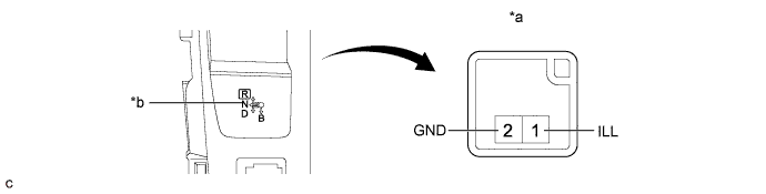
Text in Illustration *a Component without Harness Connected
(Position Indicator Housing Assembly)
*b Position indicator housing assembly illumination
-
Apply battery voltage between the terminals of the switch, and check the illumination condition of the combination switch assembly.
Standard Measurement Condition Specified Condition Auxiliary battery positive (+) →Terminal E115-1 (ILL+)
Auxiliary battery negative (-) →Terminal E115-2 (ILL-)
illuminates If the result is not as specified, replace the combination switch assembly.
-
-
-
INSPECT SEAT HEATER SWITCH
-
Check operation of the seat heater switch.
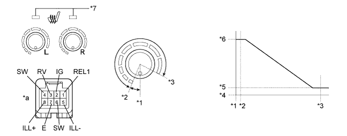
Text in Illustration *1 0°(Off) *2 27°(On (Min.)) *3 300° (On(MAX.)) *4 0 kΩ *5 0.28 to 0.42 kΩ *6 2.72 to 4.08 kΩ *7 Seat Heater Switch Indicator - - *a Component without harness connected
(Seat Heater Switch)
- -
-
Measure the resistance according to the value(s) in the table below.
Standard Resistance LH Side Tester Connection Switch Condition Specified Condition 3 (RV) - 4 (SW) Off 2.72 to 4.08 kΩ 3 (RV) - 4 (SW) On (Min.) 2.72 to 4.08 kΩ 3 (RV) - 4 (SW) On (Max.) 0.28 to 0.42 kΩ RH Side Tester Connection Switch Condition Specified Condition 1 (REL1) - 6 (SW) Off 2.72 to 4.08 kΩ 1 (REL1) - 6 (SW) On (Min.) 2.72 to 4.08 kΩ 1 (REL1) - 6 (SW) On (Max.) 0.28 to 0.42 kΩ If the result is not as specified, replace the seat heater switch.
-
-
Check operation of the seat heater switch indicator.
-
Apply auxiliary battery voltage and check operation of the switch as shown in the table below.
Standard Measurement Condition Switch Condition Specified Condition Auxiliary battery positive (+) → Terminal 2 (IG)
Auxiliary battery negative (-) → Terminal 7 (E)
Seat heater switch on Indicator comes on If the result is not as specified, replace the seat heater switch.
-
-
Check the illumination of the seat heater switch.
-
Apply auxiliary battery voltage and check operation of the switch as shown in the table below.
Standard Measurement Condition Specified Condition Auxiliary battery positive (+) → Terminal 8 (ILL+)
Auxiliary battery negative (-) → Terminal 5 (ILL-)
Illumination comes on
-
-